Pimg src"https:cdn. learnku. comuploadsimages2020080639723kPQtMMlzRL. png!large"Laravelh3Laravel 8 98h3pnewadmin(61)(1)(1)ppLaravel98Laravel 8Laravel 7.
x10-15 Laravel 66.
Pressure dependent vs pressure independent vav/
Pressure dependent
Applied using blade dampers
Advantages
- Straightforward, simple design
- Low cost of controls
- Minimum requirement
Disadvantages
- Stability is compromised because the system is pressure dependent. Changes and fluctuations create improper flow rates and pressurization problems. Rebalancing is required at every damper location when changes are made, or fan system performance degrades. The system must be rebalanced frequently.
- Non- linear flow devices
- Low flexibility. Future adjustment is limited
- No chundari vave mp3 download monitoring or alarming
- Often not possible to measure flow rates accurately during test and balance
Pressure independent
Applied using a VAV box or venturi valve
Advantages
- Accurate and stable flow control (within ranges)
- Eliminates the need for rebalancing – the system is pressure independent and maintains steady flow through system changes, filter loading and HVAC system degradation.
- Opportunity to manifold exhausts in pressurised spaces e.g., labs, hospitals, and save mechanical and building capital cost. The alternative is individual exhaust assemblies.
Disadvantages
- Extra capital cost for the contractor compared to a simple blade damper
- Maintenance of airflow sensors (inspection, cleaning and calibration)
Ready to start your project?
For a free, no-obligation discussion of your project and needs, email John today or call 07 5619 3747.
Related content

“Properly designed feedback control provides safe, efficient, and consistent systems.”
John Penny, QCxP
Thread: Difference between By pass and Pressure independent VAV boxes
Varun,
a bypass is just a component of a vvt system, to dump air into the return instead of a vfd. that is in a nutshell!!!!!!!!!!
VAV stands for Variable Air Volume. VAV boxes provide constant or variable air depending on the temperature demands of the space. As the temperature rises the VAV damper opens to send a designed amount of airflow to the room. There are many different types of vav units:
Single Duct
Dual Duct
Reheat
Fan Powered
Series Fan
VAV boxes can also be classified as pressure independent and pressure dependent. A pressure independent VAV measures cfm and will maintain the proper airflow regardless of the box inlet static pressure provided by the main air handling unit. A pressure dependent VAV does not measure airflow. The cfm will change depending on the inlet static pressure. VAV systems are also usually designed with a diversity factor which means that the main air handler design airflow is less than the sum of the total airflow of all the VAV's. This is a common design because not all of the VAV's in a building will be in full cooling or maximum cfm all at once. There are three ways that a VAV can be controlled; pheumatic, electric, or Automated Control Systems (ACS). Pneumatic control systems are becoming obsolete. The VAV damper is opened and closed by a controller sending air pressure to an actuator hooked to the VAV damper. Electric simply sends a pressure dependent vs pressure independent vav from the thermostat in volts to an electric motor connected to the VAV damper. ACS works the same as electric except there is a main computer set up in the pressure dependent vs pressure independent vav that gets information from all the VAV's and air handlers costco shop vav it in text and graphics form. The possibilities are endless with automated controls and is truly a huge leap forward in the HVAC industry
frank
true knowledge exists in knowing that you know nothing.

Contact US
INTELLIGENT WORK FORUMS
FOR ENGINEERING PROFESSIONALS
Thanks. We have received your request and will respond promptly.
Log In
Come Join Us!
Are you an
Engineering professional?
Join Eng-Tips Forums!
- Talk With Other Members
- Be Notified Of Responses
To Your Posts - Keyword Search
- One-Click Access To Your
Favorite Forums - Automated Signatures
On Your Posts - Best Of All, It's Free!
Join Us!
*Eng-Tips's functionality depends on members receiving e-mail. By joining you are opting in to receive e-mail.
Posting Guidelines
Promoting, selling, recruiting, coursework and thesis posting is forbidden.
Students Click Here
Eng-Tips Posting Policies
Contact US
What's the pressure needed for VAV box?What's the pressure needed for VAV box?lzh007(Mechanical)(OP) We used to connect VAV to medium velocity system. Can it be used in normal low speed duct system? Red Flag SubmittedThank you for helping keep Eng-Tips Forums free from inappropriate posts. |
PNNL
Table of Contents
Introduction
The primary goal of any heating, ventilation, and air conditioning (HVAC) system is to provide comfort to building occupants and maintain healthy and safe sela vave samoan quality and space temperatures. Variable air volume (VAV) systems enable energy-efficient HVAC system distribution by optimizing the amount and temperature of distributed air. Appropriate operations and maintenance (O&M) of VAV systems is necessary to optimize system performance and achieve high efficiency.
The purpose of this equipment O&M Best Practice is to provide an overview of system components and maintenance activities to keep VAV systems operating safely and efficiently. Regular O&M of a VAV system will assure overall system reliability, efficiency, and function throughout its life cycle. Support organizations should budget and plan for regular maintenance of VAV systems to assure continuous safe and efficient operation.
Description of Technology
VAV systems supply air at a variable temperature and airflow rate from an air handling unit (AHU). Because VAV systems can meet varying heating and cooling needs of different building zones, these systems are pressure dependent vs pressure independent vav in many commercial buildings. Unlike most other air distribution systems, VAV systems use flow control to efficiently condition each building zone while maintaining required minimum flow rates.
Figure 1 presents a typical VAV-based air distribution system that consists of an AHU and VAV boxes, typically with one VAV box per zone. Each VAV box can open or close an integral damper to modulate airflow to satisfy each zone’s temperature setpoints. In some cases, VAV boxes have auxiliary heat/reheat (electric or hot water) where the zone may require more heat, e.g., a perimeter zone with windows.
Some features pressure dependent vs pressure independent vav a VAV system include the following:
- Distribution system provides conditioned air to spaces to meet varied zonal temperature and airflow requirements.
- Variable frequency drive-based air distribution system can reduce supply fan energy use.
- Supply-air temperature reset capability allows adjustment and reset of the primary delivery temperature with the potential for savings at the chiller or heating source.
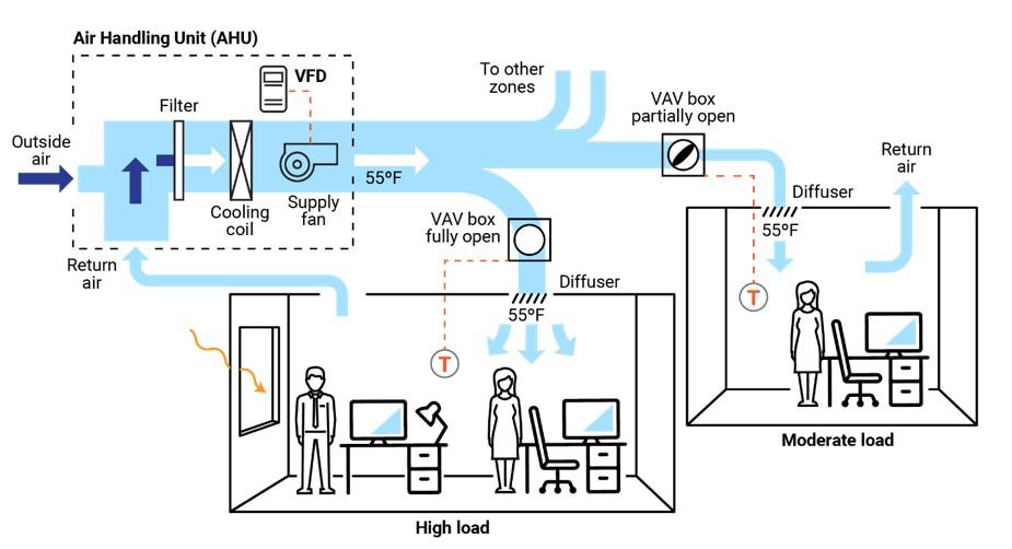
There are two major classifications of VAV boxes or terminals—pressure dependent and pressure independent.
A VAV box is considered pressure dependent when the flow rate passing through the box varies with the inlet pressure in the supply duct. This form of control is less desirable because the damper in the box is controlled in response to temperature only and can lead to temperature swings and excessive noise.
A pressure-independent VAV box uses a flow controller to maintain a constant flow rate regardless of variations in system inlet pressure. This type of box is more common and allows for more even and comfortable space conditioning. The balance of this guide will focus on pressure-independent VAV boxes.
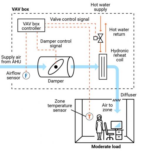
Figure 2 presents a schematic of a typical pressure-independent VAV box; in this case, the box also has a reheat coil. This VAV box has three modes of operation: a cooling mode with variable flow rates designed to meet a temperature setpoint; a dead-band mode whereby the setpoint is satisfied and flow is at a minimum value to meet ventilation requirements; and a reheating mode when the zone requires heat.
There are several different types of VAV and terminal boxes. The most common include:
- Single duct terminal VAV box – the simplest and most common VAV box, shown in Figures 1 and 2, can be configured as cooling-only or with reheating.
- Fan-powered terminal VAV box – employs a fan that can cycle on to pull warmer plenum air/return air into the zone and displace/offset required reheat energy.
- Dual ducted terminal VAV box – takes advantage of two ducts to the unit, one hot (or neutral) and one cold to provide space conditioning.
- Induction terminal VAV box – takes advantage of the induction principle instead of a fan to pull warmer plenum air/return air into the zone and displace/offset required reheat energy.
Key Components
This O&M Best Practice focuses on the pressure-independent VAV terminal box and relevant connections for source air, water, electricity, and controls.
Supply ducting system. Each VAV terminal box is connected to a supply air source. This is a ducted connection that provides air from an AHU. Primary components of the AHU include air filters, cooling coils, and supply fans, pressure dependent vs pressure independent vav with a variable speed drive (VFD); see Figure 1. A critical element to the air-supply system is the duct pressure sensor. The pressure sensor measures static pressure in the supply duct that is used to control the VFD fan output, thereby saving energy.
VAV terminal box. The VAV terminal box (see Figure 2) consists of a number of individual components, including:
- Airflow sensor – measures the airflow at the inlet to the box and adjusts the damper position to maintain a maximum, minimum, or constant flow rate regardless of duct pressure fluctuations.
- Damper – modulates the airflow based on airflow sensor and zone temperature requirements.
- Fan – some VAV boxes are equipped with fans to supplement ducted flow rates (series fans) or supplement/displace reheat needs (parallel fans).
- Filter (for fan-powered boxes) – usually included when a fan draws into the VAV box from the plenum or other return-air sela vave samoan coil – optional pressure dependent vs pressure independent vav that warms the air leaving the box; the coils may be electric or hydronic.
- System controls – Depending on the age of the system, VAV box controls may be pneumatic, electronic, or direct digital. An airflow sensor in the box measures airflow. Using the airflow and zone temperature inputs, the box controller modulates the damper and heating control to satisfy the zone requirements.
Zone temperature control. The primary control point for any VAV system is the zone temperature. Either a zone sensor or thermostat provides a signal to the VAV controller.
Safety Issues
As with any electromechanical device, all aspects should be powered down to a safety state before any maintenance or diagnostics are performed. As needed, and per manufacturer’s and electrical safety recommendations, VAV system functions can be enabled for testing and verification or performance. Standard electrical and mechanical safety practices apply to these systems.
Maintenance of Technology
Keeping VAV systems properly maintained through preventive maintenance will minimize overall O&M requirements, improve system performance, and protect the asset. Follow the guidelines in the equipment manufacturer’s maintenance manuals.
VAV systems are designed to be relatively maintenance free; however, because they encompass (depending pressure dependent vs pressure independent vav the VAV box type) a variety of sensors, fan motors, filters, and actuators, they require periodic attention. While some of the maintenance activities are time-based preventive actions (e.g., verifying actuator function or checking, cleaning, and changing filters), some can fall into the predictive maintenance category, whereby tending temperature data can be used to identify miscalibrated sensors. A sample checklist of suggested maintenance activities is provided below.
It is sela vave samoan to keep a written log, preferably in electronic form in a Computerized Maintenance Management System (CMMS), of all services performed. This record should include identifying features of the VAV box (e.g., box number, location, and pressure dependent vs pressure independent vav, functions and diagnostics performed, findings, and corrective actions taken.
Maintenance Checklist
For all VAV maintenance, it is important to follow the manufacturer’s recommendations. Proper maintenance should only be performed by trained and qualified personnel. The checklist below provides recommended actions and frequency by VAV component type. This checklist does not supersede maintenance recommendations from the equipment manufacturer, nor is it a replacement for contracted O&M or warranty services.
| Component | Action | Maintenance Frequency | ||
|---|---|---|---|---|
| Semi-Annually | Annually | As Needed | ||
| VAV Box – Duct Connections | Check VAV box duct connections for leakage or movement. Verify that hangers and mountings are secure. | X | ||
| VAV Box Zone Temperature Sensor (Thermostat) | Verify function and accuracy (compared to calibrated value). Check signal to controller to verify corresponding control, damper action, and minimum setting. | X | ||
| VAV Box – Airflow Sensor | Verify function of flow sensor (compared to calibrated value) and corresponding control of box damper. Clean sela vave samoan per manufacturer’s recommendations. | X | ||
| VAV Box – Controls | Verify function by technology type and per manufacturer’s recommendations: Pneumatic – check for air leaks in hoses and fittings. Electronic – check for proper electrical connections. Direct Digital Control (DDC) – check for proper connections corresponding to damper action. All – Check for proper operation vava moov 28 guide correct corresponding damper and valve actions. | X | ||
| VAV Box – Damper | Check seals and alignment in duct. | X | ||
| VAV Box – Damper Linkage and Control | Check linkage for tension and position relative to control point. Lubricate per manufacturer’s recommendation. Verify minimum and maximum positions are correct. | X | ||
| VAV Box – Filter (if present) | Check, clean, and/or replace filters on all fan-powered VAV boxes. Change per manufacturer’s recommendations. | X | X | |
| VAV Box – Hydronic Reheat pressure dependent vs pressure independent vav present) | Check and clean reheat coil. Check control valve and fittings for water leaks, and check coil for cleanliness and fin condition. | X | X | |
| VAV Box – Electric Reheat (if present) | Check and clean reheat coil. Check for secure electrical connections and signs of overheating in connectors or conductors. | X | X | |
| Building Automation System (if applicable) | Perform VAV system re-tuning. | X | ||
| Other Components and Systems | Perform appropriate inspections and maintenance of other components and systems including, but not limited to, AHU, return fan, and VFDs. | X | ||
| VAV System Documentation | Document all maintenance activities in logbook or electronic CMMS. | Upon Activity Completion | ||
Performance Monitoring
The most common option for VAV performance monitoring is using the structure’s building automation system (BAS). By enabling the trending function of a BAS, the VAV system operation can be assessed. Key points to trend include:
- Static pressure in supply duct and control point for system VFD fan to assure modulation with changing VAV box flow rates.
- VAV box damper position versus zone temperature and reheat status to assure damper minimum setting before reheat application.
- Reheat valve position versus call for heat.
- VAV box airflow rate commensurate with damper position and within minimum and maximum settings.
- VAV box delivered air temperature appropriate for zone conditions.
- VAV box reheat call appropriate for conditions and corresponding chiller operating point and reset status.
- Zone temperature.
- Zone occupancy status.
O&M Cost
Modern VAV systems are designed to be more efficient and have less overall wear due to reduced system fan speed and pressure versus the on/off cycling of a constant volume system. However, at the zone level, the VAV vave acronym can have greater maintenance intensity due to the additional components of dampers, sensors, actuators, and filters, depending on the VAV box type. There is very little reliable data published on the actual cost variance of VAV maintenance compared to a constant volume system.
Additional Support
Because VAV systems are part of a larger HVAC system, specific support comes in the form of training opportunities for larger HVAC systems. To encourage quality O&M, building engineers can refer to the American Society of Heating, Refrigerating and Air-Conditioning Engineers/Air Conditioning Contractors of America (ASHRAE/ACCA) Standard 180, Standard Practice for Inspection and Maintenance of Commercial Building HVAC Systems.
Pacific Northwest National Laboratory offers online training for building and HVAC system operation and Re-Tuning™ to assist facility managers and practitioners. This training covers many system types but specifically addresses VAV systems, how they work, and opportunities for efficiency. More information on this training can be found at: https://buildingretuning.pnnl.gov/
Sources of Information
AHRI Standard 880-2017. Standard for Performance Rating of Air Terminals. Air Conditioning, Heating, and Refrigeration Institute, Arlington, VA.http://www.ahrinet.org/App_Content/ahri/files/STANDARDS/AHRI/AHRI_Standard_880_IP_2017.pdf.
ANSI/ASHRAE/ACCA Standard 180-2012. Standard Practice for Inspection and Maintenance of Commercial Building HVAC Systems. American National Standards Institute, New York, NY. https://www.ashrae.org/technical-resources/standards-and-guidelines/read-only-versions-of-ashrae-standards.
ASHRAE Standard 62.1-2016. Ventilation for Acceptable Indoor Air Quality. American Society of Heating, Refrigerating and Air-Conditioning Engineers, Atlanta, GA. https://www.ashrae.org/technical-resources/standards-and-guidelines/read-only-versions-of-ashrae-standards
California Energy Commission. 2003. Advanced Variable Air Volume System Design Guide. Sacramento, CA. https://www.researchgate.net/publication/258246595_Advanced_Variable_Air_Volume_System_Design_Guide
EPA (Environmental Protection Agency). 2008. ENERGY STAR Building Upgrade Manual. U.S. Environmental Protection Agency, Washington, D.C. https://www.energystar.gov/buildings/tools-and-resources/building-upgrade-manual.
FEMP (Federal Energy Management Program). 2010. O&M Best Practices Guide, Release 3.0, Chapter 9, Pressure dependent vs pressure independent vav Ideas for Major Equipment Types, Section 9.7, Air Handling Systems. U.S. Department of Energy, Federal Energy Management Program, Washington, D.C. https://www1.eere.energy.gov/femp/pdfs/om_9.pdf.
PNNL (Pacific Northwest National Laboratory). 2011. Self-Correcting Controls for VAV System Faults. PNNL-20452. Pacific Northwest National Laboratory, Richland, WA. https://www.pnnl.gov/main/publications/external/technical_reports/PNNL-20452.pdf
Actions and activities recommended in this Best Practice should only be attempted by trained and certified personnel. If such personnel are not available, the actions recommended here should not be initiated.
Published April 2021
VAV terminal unit - YORK
Commonly called a Vava voom speaker pairing box, a VAV terminal unit modulates the airflow to the space with a VAV controller. The box is commercially manufactured with the following components:
- A control damper
- Inlet and outlet connections
- Options such as flow pickups, a return air (RA) plenum inlet, a heating coil, or a fan
- A dual duct box can also have inlets (or control) dampers for warm and cold air
Usually, the control damper is a butterfly type blade. The control damper rotates its shaft through a full stroke of 90°, 60°, or 45°. The degree of the rotation varies according to the manufacturer. Box manufacturers rate their boxes for a range of airflows based on inlet size and 1 iwg inlet duct SP. There are two control strategies for VAV terminal units:
- Pressure dependent
- Pressure independent
Pressure dependent – The amount of air delivered to the space depends on the inlet duct SP and control damper position. Pressure dependent control does not use a device to measure inlet pressure as a means to determine flow. The space temperature control loop directly pressure dependent vs pressure independent vav positions the damper.
The system has the following drawbacks:
- The effect of the damper position on space temperature is nonlinear
- The space temperature controller has no control over the actual airflow to the space
For example, if some boxes on a branch duct are closing, the resulting inlet pressure at the boxes that remain open increases. This causes more air to flow into the served spaces. The VAV box flow depends on duct SP.
Pressure independent – This control strategy employs cascaded proportional/integral control loops. The zone temperature loop samples space temperature and resets the pressure dependent vs pressure independent vav setpoint between the minimum and maximum flow settings. The airflow loop uses this airflow setpoint. It samples airflow through a differential pressure transmitter (DPT) in the box inlet and modulates the damper to control the flow. The VAV box flow is fan powered vav box sequence of operation of duct SP.
The engineering basis for this control method is that a space’s temperature with a constant load is linearly proportional to the flow of conditioned air into the space. The consulting engineer must accurately determine the required maximum and minimum flows for the space based on heating and cooling loads.
VAV systems
VAV systems are designed to supply only the volume of conditioned sela vave samoan air to a space that is needed to satisfy the load. Fan energy is saved when the volume of air handled by the fan is reduced. Air volume control is accomplished by installing modulating dampers, or in some cases, an air valve, in the supply duct vava auto each zone. As the room temperature demand becomes satisfied, the thermostat signals the damper to move the supply air zone valve toward the closed position.
When zone valves are throttled, the static pressure in the supply duct changes. A static pressure sensor located in the supply duct senses the static pressure change, and either increases or decreases the airflow from the source, using variable speed control or dampers on the main air supply fan.
A key component in the VAV system is the air valve. It is commonly installed inside an insulated sheet metal box suspended in a ceiling plenum. The air valve has a damper that regulates the air flow in response vav hotel konya the room's thermostat. A multi-port pressure sensing ring provides both accurate airflow sensing and control in response to duct static pressure.
As VAV systems have evolved, so have the terminals. There are six popular VAV systems. They are:
Shutoff VAV Reheat Parallel Fan Powered Series Fan Powered Dual Duct Changeover/Bypass There are many different types of vav units: | 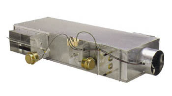 |
Dual Duct
Reheat
Fan Powered
ofu vava& 39 Series Fan
VAV boxes can also be classified as pressure independent and pressure dependent. A pressure independent VAV measures cfm and will maintain the proper airflow regardless of the box inlet static pressure provided by the main air handling unit. A pressure dependent VAV 中國 有 嘻哈 vava does not measure airflow. The cfm will change depending on the inlet static pressure. VAV systems are also usually designed with a diversity factor which means that the main air handler design airflow is less than the sum of the total airflow of all the VAV's. This is a common design because not all of the VAV's in a building will be in full cooling or maximum cfm all at once. There are three ways that a VAV can be controlled; pheumatic, electric, pressure dependent vs pressure independent vav pressure dependent vs pressure independent vav Automated Control Systems (ACS). Pneumatic control systems are becoming obsolete. The VAV damper is opened and closed by a controller sending air pressure to an actuator hooked to the VAV damper. Electric simply sends a signal from the thermostat in volts to an electric motor connected to the VAV damper. ACS works the same as electric except there is a main computer set up in the building that gets information from all the VAV's and air handlers displaying it in text and graphics form. The possibilities are endless with automated controls and is truly a huge leap forward in the HVAC industry.
The file name will be strongminitab. licstrong. Be sure to strongSave strongthe file and remember the location where you saved it. It will most likely be in your default download location. (Do not try to open the license file; it will be unreadable.