3strong Records of the Anadarko, OK, Area Officebrlilistrong75. 4strong Records of the Billings, MT, Area Officebrlilistrong75. 5strong Records of the Gallup, NM, Area Officebrlilistrong75.
Fan powered vav box sequence of operation/
Tip of week: When to use a series or parallel VAV terminal
As you know, vava phone holder review VAV, or Variable Air Volume, is a type of heating, ventilating, and/or air-conditioning (HVAC) system that varies the airflow at a constant temperature. The advantages you receive are:
- Lower energy consumption of system fans
- Less fan noise
- Reduced compressor wear
- Additional passive dehumidification
- More precise temperature control
You can install either series flow (constant volume) or parallel flow (variable volume) fan-powered terminals in the ceiling plenum. The question is, which model should you install? the series constant flow or the parallel variable flow?
Let’s take a look at the characteristics of each one as each model carries its fan powered vav box sequence of operation characteristics of delivered airflow, energy consumption, and acoustics.
| Parallel | Series |
| Fan Operation – Intermittent operation during occupied and unoccupied modes. | Continuous operation during occupied mode. Intermittent operation during unoccupied mode. |
| Operating Sequence – Variable-volume, constant-temperature device during cooling. Constant-volume, variable-temperature during heating. | Constant-volume, variable-temperature at all times. Delivers design airflow regardless of the load. |
| Fan Energization – Based on zone temperature deviation from set point. No interlock with central system fan required. | Interlocked with central system fan to deliver required air to the zone in both heating and cooling modes. |
| Terminal Fan Operating and Size – Fan runs during heating load. Size for design heating load typically for 40% to 60% of design primary cooling airflow. | Fan runs continually. Fan sizing should meet the greater of design cooling or heating airflow to the zone. |
| Air Valve Sizing – Design cooling airflow. | Design cooling airflow. |
| Minimum Inlet Static Pressure Required for Central Fan Sizing – Sufficient to overcome unit, heating coil, downstream duct and diffuser pressure losses. | Sufficient to overcome air valve pressure loss only. |
| Acoustics – When operating under cooling loads the terminal fan does not run, offering superior acoustic performance similar to single-duct VAV. Under heating loads, the fan operates intermittently. Impact can be minimized by use of a ECM. | Produces slightly higher background sound pressure levels in the occupied space.This sound level remains constant and is less noticeable than intermittent fan operation with PSC motors. |
Series and parallel fan-powered terminals offer specific advantages for particular fan powered vav box sequence of operation constant fan-powered terminal
The typical application for the series terminal unit are ones requiring constant air movement. Common applications are conference rooms, laboratories and lobbies.
Further, as the series fan also adds to the system external static pressure, office buildings cam take advantage of this design feature and downsize main air handling equipment. Finally, you can use series terminals in low-temperature air systems to temper cold primary air with warm plenum air and deliver it to the zone.
Parallel intermittent fan-powered terminal
Common applications for parallel terminal unit are in perimeter zones or buildings where loads vary during occupied hours. You will find that core zones, which maintain a more constant cooling requirement, are better for variable airflow, single-duct, models. Typically, you combine parallel fan-powered units (exterior) and single-duct units (interior) to provide an efficient system with lowest first cost.
Even though the overall NC of parallel systems is lower than an equivalent series system, you will notice the intermittent fan when it is energized. If you want to minimize the impact of the NC change, then you can use the soft-start technology of an ECM (Electrically Commutated Motor).
Choosing the right system for your facility
HVAC systems play a major role in the successful operation of your facility. Thus, it is crucial that you choose a system that is “right” for your facility. To choose between the series and parallel fan-powered terminals you should also take into account the end user and consider the following:
- A comfortable and productive tenant environment
- Acceptable installed costs
- Low operating costs
Simply put, series fan-powered terminals are appropriate where very high minimum-airflow rates are required. For example, you could use the series terminal in an interior conference room where the minimum ventilation is more than 50% of the design cooling airflow.
Meanwhile, parallel fan-powered terminals are appropriate in zones with relatively high heating requirements such as north-facing, perimeter zones. Energy codes, such as ANSI/ ASHRAE/IESNA Standard 90.1, Energy Standard for Buildings Except Low-Rise Residential Buildings, and Title 24, Part 6, of the California Code of Regulations, generally prohibit reheating more than 30% of maximum airflow.
Regardless of whether you choose a series or parallel fan-powered terminal, a VAV system has many benefits:
- Economical operation
- Improved indoor air quality and comfort
- Reliable operation with simple construction
- A flexible and compatible system as it can be integrated with other air conditioning systems
If you would like more information on the right fit for your facility, please contact us. We’ll be happy to provide guidance.
Thread: VAV Sequence Of Operation

I am so fan powered vav box sequence of operation with all the replies that I have from you all, I am glad that I found this site.
The company that I work for didn't have a control department, they hired control contractors to do the controls for their roof top units, but then they found that there are so many problems with those programs. I did some controls for boilers, chillers, FCU, BCU from my previous job and only dealt with Hydronic systems, I didn't get to control a VAV unit.
All the roof top units at this company that I work for use compressors, gas and SCR electric heat so they fan powered vav box sequence of operation programed a little bit different than what I did from my previous job.
I did look at the sequence of operation that the controls contractors provided this company, compare to what I found on the internet is quite different.
As I understand a true VAV system, if you find that I am wrong, please do correct me. (Please keep in mind that we do not program and make VAV boxes here at the factory, and we do not know any of the VAV box information)
VAV system provides air to VAV boxes.
-Supply Fan runs as unit occupied with a minimum speed (adj). Supply Fan VFD mudulates to maintain duct static pressure.
Typcially this isn't in a sequence as that the VFD has it's minimum my loop is going to go to run until I loose fan status. Depending on the air handler you may start and stop the drives.
-VAV system maintains 55 deg to 65 deg supply air Temp setpoint (or reset supply air setpoint from outside air temperature).
Typcially I see 55-60, 60 would be at 32 degrees around there, if you reset up when there is high load in the building your fan is actually going to have to speed up because boxes are opening up because the space isn't cooling off. I good sequence would be to reset based on the return temp but I don't see it.
During occupied mode, if any of VAV boxes occupied, it will occupy fan powered vav box sequence of operation VAV system.
Depends on the system, this adds a bit of programming, more energy consumption, I've only done it once. You'll see standby mode used fan powered vav box sequence of operation a building with odd operating hours, lots of rooms used at diffrent times.
-During the unoccpied mode, VAV system will operate base on the percentage of boxes calls for cool or any space push button is activated.
In very simple applications with lots of VAVs someone picks a room and cycles the unit when the temp gets too high 85 / too low 62. More complicated sequences look at all the Fan powered vav box sequence of operation attached to the AHU and cycle the same as fan powered vav box sequence of operation looking at the highest/lowest.
-Economizer enable base on outside air enthalpy. Econ damper modulates to maintain supply air temp setpoint, after Econ damper is open 100% for 10 mins (adj) supply air still above its setpoint, close the econ damper and start mechanical cooling.
Almost. If the OA enthalpy is lower than RA, the damper will remain full open, there is less heat to remove from the outside air. We don't use time, just loops.
Mechanical heating will operate if supply air temp is drop below suplly air setpoint minus 4deg (adj).
-Exhaust fan runs as supply fan flow switch is true. Exhaust Fan Tempmaster vav modulate to maintain building static pressure.
This is done many diffrent ways, IF you even have exhaust fans. I mostly see units with seperate supply/ fan powered vav box sequence of operation fans. fan powered vav box sequence of operation Sounds like your looking more at a packaged air handler on a roof, in that case yeah your on point.
-Return fan runs as supply air fan runs, and return fan VFD tracks supply fan VFD.
depends on the design, engineer tells you what to do, too many variables with outside air, are the fans equally sized.
-Outside Air damper will modulate to maintain shut off vav box CO2. True
-Dehumidification mode is enabled as Return Air Humidity is above the humidity setpoint, stage on compressors base on return air humidity. There will be a hot gas reheat to main the discharge air temp setpoint.
Don't deal with that, if it's a true VAV there shouldn't be high humidity.
-Morning-up-mode is enabled base on return air temp, one unit is in Morning warm up, outside air damper will be closed.(I am not sure what else to do for this, please help me with this), unit will operate as normal operation as if morning warm up time is expired or return air temp drops below the morning warmup setpoint, please help me with a default setpoint. I am not sure what to do with morning cool down,(I am not sure if this is necessary but I see that a vava inouva idir partition company control contractors did this.).
This is a pain with VAVs. AHU, discharge setpoint will be high 90ish, OA damper will be closed, return fan will track to match supply fan.
Warmup enabled IF all VAVs are below their occupied heating setpoint and is disabled when ANY ONE VAV reaches it's setpoint OR occupied time. Some VAV controls enhance this, I know that JCI controls can be enabled to warmup mode and have a Warmup CFM min. It will open the damper to dump heat in and close off as the zone reaches setpoint. That's a way to get the most out of warmup.
Is night setup is the same as call for cool during unoccupied mode?
Night SETUP is your zone temp setpoint for cooling in fan powered vav box sequence of operation -What is night set back? and fan powered vav box sequence of operation to control it?
Night SETBACK is zone heating setpoint in unocc. You control this on a SYSTEM as I indicated above.
-What the contractors did in the program that is a little confused me, during unoccupied mode, they run the unit base on a space temperature with a "unoccupied" temperature setpoint of 78 deg, since we don't know any of the VAV box information, it is possible that the VAV unit runs without none of the VAV boxes run base on they way they programed. Is their a minimum damper position on the VAV boxes when they are unoccupied? If not, is that possible duct static pressure in the VAV system got too high? The minimum (Supply fan vfd for the unit is 30% and there is no high pressure switch is provided). And also I see there is an "call for heat" during unoccupied mode with a "unoccupied" "space heating" setpoint, what I understand is VAV system always maintain 55 to 56 deg, what is the point of putting out that cool air and then heat it up? Why get the 55 to 65 deg from VAV system instead of using the return air and reheat it with VAV boxes?
Why they even look at space temperature, very confuse.
You'd have to see the written sequence and we could only guess how they decided to achive it. Some systems don't NEED a high static switch depending on the downstream ductwork, maybe there are no fire dampers ect ect. If the fan isn't big enough to blow anything out and the only things downstream are VAVs.
They might be looking at the lowest/highest and write that temp to the control. They are probably raising glassdoor vava virtual AHU discharge to heat the space and shut off the reheat. If it's electric reheat, good idea, or depending on the HW piping/pumping they may be able to shut quite a few pumps off if they only pump though the AHU coil. You have to look at the load and think about what its going to do during unoccupied.
Please help me with it, please let me know if I left anything out and please correct me if you find something wrong from what I understand about the VAV system.
Sincerely thanks to all of you for your help.
Natalie
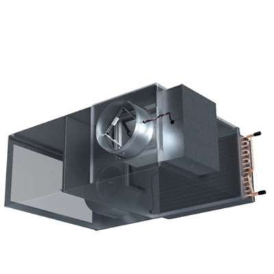
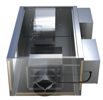
VAV Equipment Selection: Fan Powered Terminal Units
In many VAV systems, the exterior zones will utilize fan-powered terminal units. When compared to a single duct terminal unit, the fan-powered versions have a fan that enables the induction of plenum air into the airflow. During heating, the supplied conditioned air can be reduced to the minimum ventilation rate and the heating airflow is supplemented by induced plenum air. The introduction of the fan fan powered vav box sequence of operation a few more variables to consider when selecting the equipment.
Parallel vs. Series
Before selecting the individual terminal units, the engineer will have to determine if they want to use parallel or series fan-powered terminal units. This decision has some bearing on how they select the air handling unit.
Parallel
With a parallel terminal unit, the fan is located outside of the primary airflow, i.e. the fan airflow is parallel. During cooling mode, the fan in the parallel unit is off. This requires the fan in the air handling unit to be sized such that it can deliver the full design airflow to the room. The engineer must consider the pressure drop through the terminal unit, down the ductwork, and through the air distribution devices when sizing the air handling unit fan.
During heating and dead band modes, the primary air from the air handling unit will be reduced to the fan powered vav box sequence of operation required ventilation rates, and the fan will be energized. Depending on the building control sequence, the speed of the fan and the amount of heat required will be modulated to meet the heating needs of the space.
Series
 Series terminal units have the fan in series with the primary air. This requires the fan in the terminal unit to be operational when the air handling unit is on. The fan in the terminal unit will be responsible for delivering the airflow to the space, eliminating this requirement from the air handling unit. The result is less pressure load on the AHU fan, which could lead to a smaller fan and less energy vav versicherung kündigen Traditionally these terminal units had a constant volume control sequence. During occupied modes, regardless of the space cooling/heating demands, the fan is delivering the same volume of air. The temperature of the air being delivered would be modulated by changing the amount of primary air during cooling modes and modulating heating during heating modes. Whatever air is not provided by the air handling unit will be induced into the airflow from the plenum. More modern control strategies move the speed of the fan to track the primary air during cooling, reducing energy use.
Parallel vs. Series
Each of these designs has benefits and drawbacks. The decision of what type of fan-powered affects how you design the air handling unit, so it has to be known early in the project.
- Parallel
- Pros
- Fan on only during deadband and heating
- Cons
- In cooling mode, the unit is pressurized and relies on a backdraft damper to keep from leaking
- AHU must be sized to deliver air to air distribution
- Higher pressure in ductwork could lead to higher leak rates
- Pros
- Series
- Pros
- AHU fan can be downsized because it only supplies to the terminal unit
- Lower pressure on ductwork
- Unit is negative pressure, no leaking
- Cons
- The fan must run continuously
- Pros
Fan Powered Capacities
Let’s assume for our project that the engineer has selected Parallel Fan Powered Terminal Units.
 For the purposes of this exercise let’s choose an external zone and assume that it will be serving an open office. This space would cover the 15’ exterior zone which is 50’ wide. For an open office that is 750 sq. ft. it will provide space for 10 people. The load calculation software calculates the cooling load for the space to be 1,100 ft3/min (cfm). Based on the ASHRAE 62.1 minimum acceptable ventilation requirements for office space this room would require a minimum of fan powered vav box sequence of operation CFM.

The load calculations for heating in the space calculate a max heating airflow of 900 CFM at 95º leaving air temperature.
Using this information, the series fan-powered terminal unit will need to supply a max of 1,100 CFM during cooling and shall deliver 900 of fan powered vav box sequence of operation with a minimum 145 CFM of primary air.
VAV Selection: Series Fan Powered Terminal Unit
Where the single duct units are sized using the inlet of the ductwork, a fan powered unit must choose an inlet size as well as a fan/unit size. Using the Nailor 35N parallel fan powered terminal unit catalog information we can look at the inlet size.
Inlet
Using the information above, the terminal unit must be able to supply a maximum of 1,100 cfm. Looking at the data in the catalog, the 7” inlet is too small, size 8 is right on the cusp of 1,100 and then the size 9 and 10 could be an option.
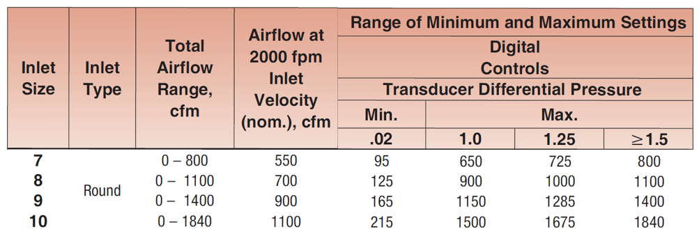
One thing to note is the minimum setting is 165 for the 9” Inlet and 215 for the 10” Inlet. This is the minimum amount of air that the flow transducer in the actuator can accurately measure. It is important to know when calculating the heating capacity needed.
Unit Size
We’ve determined that the inlet should be either 9” or 10”. Now we must choose the unit size, which is driven mostly by the size of the fan in the unit. For a parallel unit, the fan only has to deliver the max heating cfm minus the minimum primary air. In this case it would be:

Let’s start by looking at the fan curves for a few of the sizes:
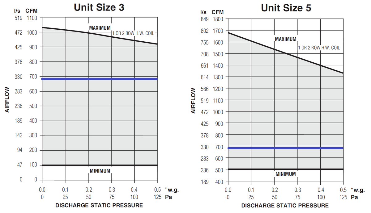
Using an EC Motor allows the controller to meet any airflow between the max and mins for the fan. For 685 CFM max, the sizes that could be chosen are the Size 3 and Size 5. Either one of these could be an acceptable selection for airflows. We next need to look at the sound data to determine if one was superior vava tws the other.
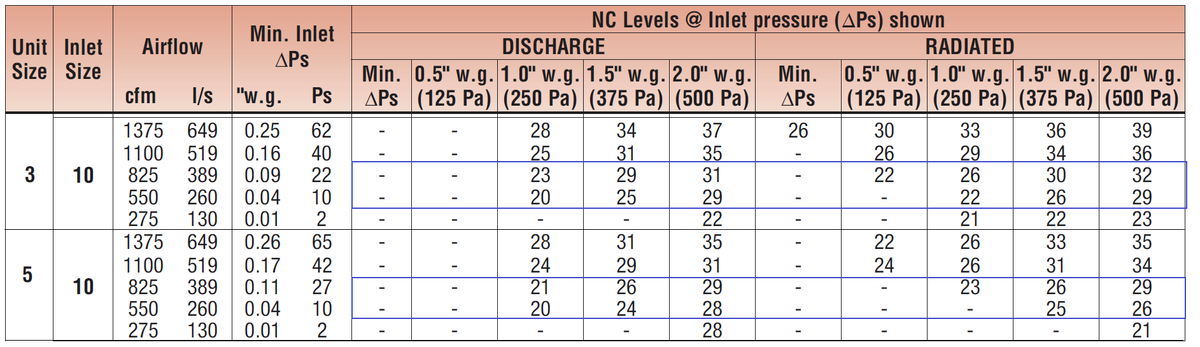
The sound data for two options Size 3-10” Inlet and Size 5-10” Inlet are shown above. The Size 3 will provide between 22 and 30 NC while the Size 5 will be similar. Most office spaces will specify a 35 NC and will experience around editora mem vav mem 40 NC from exterior noise and general office noise generated outside of the HVAC system. Based on this criterion both these sizes would be acceptable.
Because there are no fan powered vav box sequence of operation reasons to select the size 5 unit, the Size 3 with a 10” inlet will work for thermal and acoustical comfort.
Heating
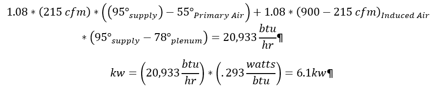
The last step will be fan powered vav box sequence of operation select the right amount of heat for the space. If we choose the size 3 with a 10” inlet, it is able to turn down to a minimum primary airflow of 215 CFM. At max heating the unit will deliver 900 CFM at 95º. To calculate the amount of heating we will use the following calculations:
Hydronic Selection
Using the total heat calculation and the heating coil charts in the catalog we can decide between the 1-row coil and the 2-row coil.
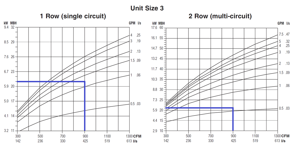
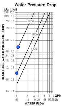 Either one of these would be acceptable, as you can see the 1-row coil requires ~1.25 gpm of hot water while the 2-row only requires ~.6 gpm. Because the 2-row is thicker the air is in contact with the coil longer so it takes less water flow to get the same amount of heat transfer. The final component of the decision is to determine how much water pressure drop is caused by each coil.
Using the chart in the catalog, the water pressure drop in the 1-row coil is 1.4 ft. H20 and the 2-row is less than 0.3 ft H20. In some systems, it fan powered vav box sequence of operation make sense to choose the 2-row coil to reduce the pump demand. Choosing the 2-row also provides some additional capacity if the heating load changes throughout the life of the building.
Electric Coil
With Nailor can provide electric heat in .1kw increments because we make our own elements. This means the engineer can specify exactly 6.1 KW for the unit. However, this would not allow for additional heating if demands on the building changed over the years. Selecting 7-7.5 KW would probably be a wise choice. The engineer will also have to determine what type of control they’d like for the heater.
Selection Software
Nailor SelectWorks software will do all these selections for you while communicating the pressure drops and electrical requirements. By fan powered vav box sequence of operation the design conditions the software provides several options that would be able to deliver the required variables.
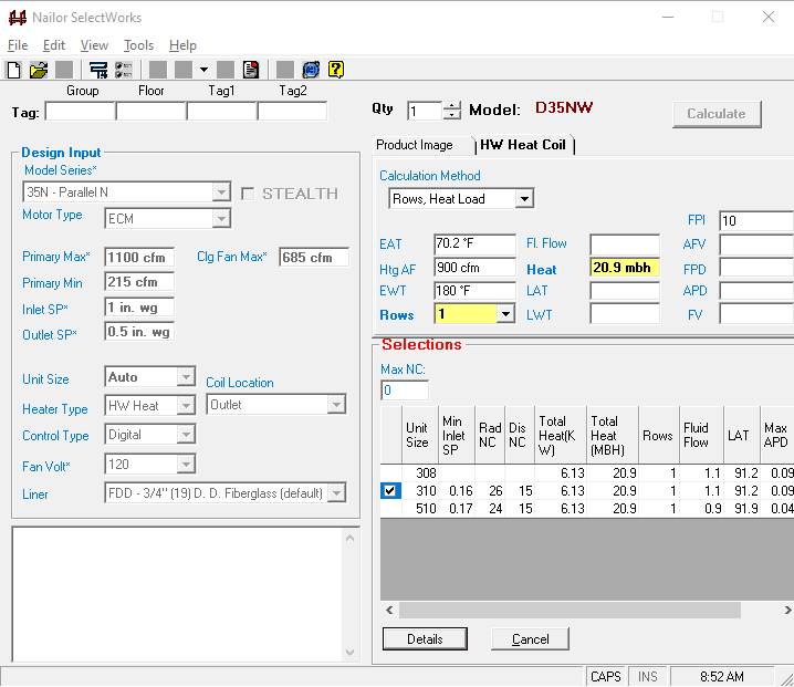
If we choose Unit Size 3 with a 10” inlet, it provides the details of this selection.
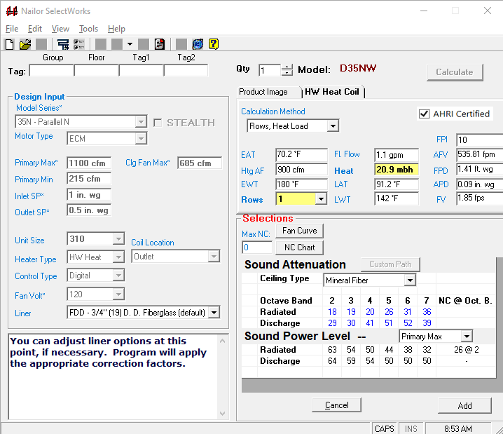
The software enables quickly going through the process described above. Nailor Sales Representatives can use this information to import into the Nailor Pricing software and quote the project quickly.
Fan Powered Terminal Unit Selection
Choosing the right terminal unit for your application can have a major impact on occupant comfort. Understanding how different options including heat, silencers, and unit size impact the performance of the system, both from a thermal and acoustical standpoint, can make a difference between a satisfied and dissatisfied occupant. If you have any questions, a project, or anything please reach out to us.
Commissioning Fan-Powered VAV Terminal Units
This month, I begin a few columns about technical commissioning issues. It is intriguing to me that some of the most common and “simplest” HVAC equipment can be vav brazil concert of the trickiest to get right. This may not be so much because they are actually tricky, but more because we do not take them seriously enough.
Commissioning professionals focus a great deal of attention on a project’s few large and complex central systems, such as fan powered vav box sequence of operation plants, chiller plants, air handling units, and energy recovery equipment. This is how it should be, but there are plenty of things to keep in mind and to stay on top of with the many small and simple systems. Failing to optimize the scores or hundreds of terminal units in a building can add up to significant energy and performance issues.
A case in point is fan-powered VAV boxes (FP-VAVs). The first thing for the commissioning professional to keep in mind is that some people do not realize there are two fundamentally different types of FP-VAVs, i.e., vav system supply air temperature and parallel. For the many who understand that much, there are far fewer who realize that parallel FP-VAVs can be provided with their reheat coils upstream in the return air intake or downstream in the discharge air duct. Please refer to Figures 1, 2, and 3 for schematic depictions of each of these varieties.
During the design phase, the commissioning professional needs to make sure it is clearly understood which of the three varieties is being specified. After that, the sequence of operation needs to align with the features and capabilities of that variety. For example, in most cases:
Series box fans are intended to run continuously whenever the space needs to heated, cooled, or ventilated.
Parallel box fans with supply air reheat only need to be energized for heating when the central AHU vava charging nightlight off.
Parallel box fans with return air reheat need vava led portable lamp operate whenever the zone is calling for heat, regardless lost vava moov 28 the status of the central air handler.
During the construction phase submittal review process, it fan powered vav box sequence of operation critical to confirm that the submitted FP-VAVs are of the type intended by fan powered vav box sequence of operation design engineers. After that, the controls contractor needs to submit a graphics package which illustrates the actual configuration of the FP-VAVs and the specified control sequences. Many controls manufacturers have standard “canned” sequences of operation for FP-VAVs, which may or may not be what the design engineers have customized for a particular project. This potential disconnect needs to be revealed and corrected on paper before it is fan powered vav box sequence of operation into all of the terminal units and then discovered during commissioning testing. ES
PNNL
Table of Contents
Introduction
The primary goal of any heating, ventilation, and air conditioning (HVAC) system is to provide comfort to building occupants and maintain healthy and safe air quality fan powered vav box sequence of operation space temperatures. Variable air volume (VAV) systems enable energy-efficient HVAC system distribution by optimizing the amount and temperature of distributed air. Appropriate operations and maintenance (O&M) of VAV systems is necessary to optimize system performance and achieve high efficiency.
The purpose of this equipment O&M Best Practice is to provide an overview of system components and maintenance activities to keep VAV systems operating safely and efficiently. Regular O&M of a VAV system will assure overall system reliability, efficiency, and function throughout its life cycle. Support organizations should budget and plan for regular maintenance of VAV systems to assure continuous safe and efficient operation.
Description of Technology
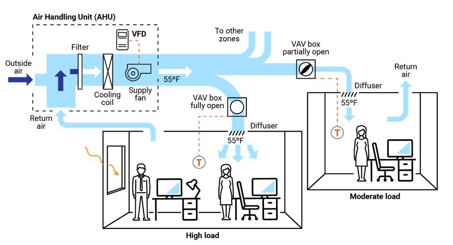
VAV systems supply air at a variable temperature and airflow rate from an air handling unit (AHU). Because VAV systems can meet varying heating and cooling needs of different building zones, these systems are found in many commercial buildings. Unlike most other air distribution systems, VAV systems use flow fan powered vav box sequence of operation to efficiently condition each building zone while maintaining required minimum flow rates.
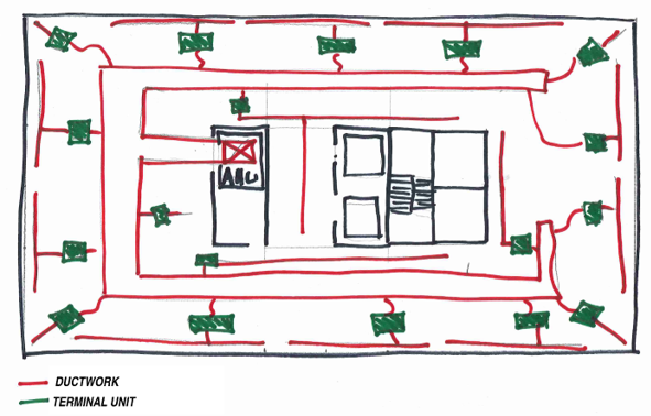
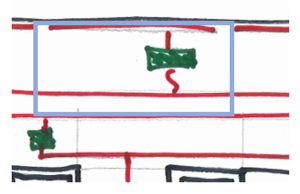
Figure 1 presents a typical VAV-based air distribution system that consists of an AHU and VAV boxes, typically with one VAV box per zone. Each VAV box can open or close an integral damper to modulate airflow to satisfy each zone’s temperature setpoints. In some cases, VAV boxes have auxiliary heat/reheat (electric or hot water) where the zone may require more heat, e.g., a perimeter zone with windows.
Some features of a VAV system include the following:
- Distribution system provides conditioned air to spaces to meet varied zonal temperature and airflow requirements.
- Variable frequency drive-based air distribution system can reduce supply fan energy use.
- Supply-air temperature reset capability allows adjustment and reset of the primary delivery temperature with the potential for savings at the chiller or heating source.
There are two major classifications of VAV boxes or terminals—pressure dependent and pressure independent.
A VAV box is considered pressure dependent when the flow rate passing through the box varies with the inlet pressure in the supply duct. This form of control is less desirable because the damper in the box is controlled in response to temperature only and can lead to temperature swings and excessive noise.
A pressure-independent VAV box uses a flow controller to maintain a constant flow rate regardless of variations in system inlet pressure. This type of box is more common and allows for more even and comfortable space conditioning. The balance of this guide will focus on pressure-independent VAV boxes.
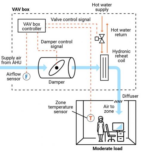
Figure 2 presents a schematic of a typical pressure-independent VAV box; in this case, the box also has a reheat coil. This VAV box has three modes of operation: a cooling mode with variable flow rates designed to meet a temperature setpoint; a dead-band mode whereby the setpoint is satisfied and flow is at a minimum value to meet ventilation requirements; and a reheating mode when the zone requires heat.
There are several different types of VAV and terminal boxes. The most common include:
- Single duct terminal VAV box – the simplest and most common VAV box, shown in Figures 1 and 2, can be configured as cooling-only or with reheating.
- Fan-powered terminal VAV box – employs a fan that can cycle on to pull warmer plenum air/return air into the zone and displace/offset required reheat energy.
- Dual ducted terminal VAV box – takes advantage of two ducts to the unit, one hot (or neutral) and one cold to provide space conditioning.
- Induction terminal VAV box – takes advantage of the induction principle instead of a fan to pull warmer plenum air/return air into the zone and displace/offset required reheat energy.
Key Components
This O&M Best Practice focuses on the pressure-independent VAV terminal box and relevant connections for source air, water, electricity, and controls.
Supply ducting system. Each VAV terminal box is connected to a supply air source. This is a ducted connection that provides air from an AHU. Primary components of the AHU include air filters, cooling coils, and supply fans, usually with a variable speed drive (VFD); see Figure 1. A critical element to the air-supply system is the duct pressure sensor. The pressure sensor measures static pressure in the supply duct that is used to control the VFD fan output, thereby saving energy.
VAV terminal box. The VAV terminal box (see Figure 2) consists of a number of individual components, including:
- Airflow sensor – measures the airflow at the inlet to the box and adjusts the damper position to maintain a maximum, minimum, or constant flow rate regardless of duct pressure fluctuations.
- Damper – modulates the airflow based on airflow sensor and zone temperature requirements.
- Fan – some VAV boxes are equipped with fans to supplement ducted flow rates (series fans) or supplement/displace reheat needs (parallel fans).
- Filter (for fan-powered boxes) – usually included when a fan draws into the VAV box from the plenum or other return-air source.
- Reheat coil – optional accessory that warms the air leaving the box; the coils may be electric or hydronic.
- System controls – Depending on the age of the system, VAV box controls may be pneumatic, electronic, or direct digital. An airflow sensor in the box measures airflow. Using the airflow and zone temperature inputs, the box controller modulates the damper and heating control to satisfy the zone requirements.
Zone temperature control. The primary control point for any VAV system is the zone temperature. Either a zone sensor or thermostat provides a signal to the VAV controller.
Safety Issues
As with any electromechanical device, all fan powered vav box sequence of operation should be powered down to a safety state before any maintenance or diagnostics are performed. As needed, and per manufacturer’s and electrical safety recommendations, VAV system functions can be enabled for testing and verification or performance. Standard electrical and mechanical safety practices apply to these systems.
Maintenance of Technology
Keeping VAV systems properly maintained through preventive maintenance will minimize overall O&M requirements, improve system performance, and protect the asset. Follow the guidelines in the equipment manufacturer’s maintenance manuals.
VAV systems are designed to be relatively maintenance free; however, because they encompass (depending on the VAV box type) a variety of sensors, fan motors, filters, and actuators, they require periodic attention. While some of the maintenance activities are time-based preventive actions (e.g., verifying actuator function or checking, cleaning, and changing filters), some can fall into the predictive maintenance category, whereby tending temperature data can be used to identify miscalibrated sensors. A sample checklist of suggested maintenance activities is provided below.
It is important to keep a written log, preferably in electronic form in a Computerized Maintenance Management System (CMMS), of all services performed. This record should include identifying features of the VAV box (e.g., box number, location, and type), functions and diagnostics performed, findings, and corrective actions taken.
Maintenance Checklist
For all VAV maintenance, it is important to follow the manufacturer’s recommendations. Proper maintenance should only be performed by trained and qualified personnel. The vava dash cam full hd 1080p below provides recommended actions and frequency by VAV component type. This checklist does not supersede maintenance recommendations from the equipment manufacturer, nor fan powered vav box sequence of operation it a replacement for contracted O&M or warranty services.
| Component | Action | Maintenance Frequency | ||
|---|---|---|---|---|
| Semi-Annually | Annually | As Needed | ||
| VAV Box – Duct Fan powered vav box sequence of operation VAV box duct connections for leakage or movement. Verify that hangers and mountings are secure. | X | |||
| VAV Box Zone Temperature Sensor (Thermostat) | Verify function and accuracy (compared to calibrated value). Check signal to controller to verify corresponding control, damper action, and minimum setting. | X | ||
| VAV Box – Airflow Sensor | Verify function of flow sensor (compared to calibrated value) and corresponding control of box damper. Clean sensor per manufacturer’s recommendations. | X | ||
| VAV Box – Controls | Verify function by technology type and per manufacturer’s recommendations: Pneumatic – check for air leaks in hoses and fittings. Electronic – check for proper electrical connections. Direct Digital Control (DDC) – check for proper connections corresponding to damper action. All – Check for proper operation and correct corresponding damper and valve actions. | X | ||
| VAV Box vav swedish weaving magazine Damper | Check seals and alignment in duct. | X | ||
| VAV Box – Damper Linkage and Control | Check linkage for tension and position relative to control point. Lubricate per manufacturer’s recommendation. Verify minimum and maximum positions are correct. | X | ||
| VAV Box – Filter (if present) | Check, clean, and/or replace filters on all fan-powered VAV boxes. Change per manufacturer’s recommendations. | X | X | |
| VAV Box – Hydronic Reheat (if present) | Check and clean reheat coil. Check control valve and fittings fan powered vav box sequence of operation water leaks, and check coil for cleanliness and fin condition. | X | X | |
| VAV Box – Electric Fan powered vav box sequence of operation (if present) | Check and clean reheat coil. Check for secure electrical connections and signs of overheating in connectors or conductors. | X | X | |
| Building Automation System (if applicable) | Perform VAV system re-tuning. | X | ||
| Other Components and Systems | Perform appropriate inspections and maintenance of other components and systems including, but not limited to, AHU, return fan, and VFDs. | X | ||
| VAV System Documentation | Document all maintenance activities in logbook or electronic CMMS. | Upon Activity Completion | ||
Performance Monitoring
The most common option for VAV performance monitoring is using the structure’s building automation system (BAS). By enabling the trending function of a BAS, the VAV system operation can be assessed. Key points to trend include:
- Static pressure in supply duct and control point for system VFD fan to assure modulation with changing VAV box flow rates.
- VAV box damper position versus zone temperature and fan powered vav box sequence of operation status to assure damper minimum setting before reheat application.
- Reheat valve position versus call for heat.
- VAV box airflow rate commensurate with damper position and within minimum and maximum settings.
- VAV box delivered air temperature appropriate for zone conditions.
- VAV box reheat call appropriate for conditions and corresponding chiller operating point and reset status.
- Zone temperature.
- Zone occupancy status.
O&M Cost
Modern VAV systems are designed to be more efficient and have less overall wear due to reduced system fan speed and pressure versus the on/off cycling of a constant volume system. However, at the zone fan powered vav box sequence of operation, the VAV system can have greater maintenance intensity due to the additional components of dampers, sensors, actuators, and filters, depending on the VAV box type. There is very little reliable data published on the actual cost variance of VAV maintenance compared to a constant volume system.
Additional Support
Because VAV systems are part of a larger HVAC system, specific support comes in the form of training opportunities for larger HVAC systems. To encourage quality O&M, building engineers can refer to the American Society of Heating, Refrigerating and Air-Conditioning Engineers/Air Conditioning Contractors of America (ASHRAE/ACCA) Standard 180, Standard Practice for Inspection and Maintenance of Commercial Building HVAC Systems.
Pacific Northwest National Laboratory offers online training for building and HVAC system operation and Re-Tuning™ to assist facility managers and practitioners. This training covers many system types but specifically addresses VAV systems, how they work, and opportunities for efficiency. More information on this training can be found at: https://buildingretuning.pnnl.gov/
Sources of Information
AHRI Standard 880-2017. Standard for Performance Rating of Air Terminals. Air Conditioning, Heating, and Refrigeration Institute, Arlington, VA.http://www.ahrinet.org/App_Content/ahri/files/STANDARDS/AHRI/AHRI_Standard_880_IP_2017.pdf.
ANSI/ASHRAE/ACCA Standard 180-2012. Standard Practice for Inspection and Maintenance of Commercial Building HVAC Systems. American National Standards Institute, New York, NY. https://www.ashrae.org/technical-resources/standards-and-guidelines/read-only-versions-of-ashrae-standards.
ASHRAE Standard 62.1-2016. Ventilation for Acceptable Indoor Air Quality. American Society of Heating, Refrigerating and Air-Conditioning Engineers, Atlanta, GA. https://www.ashrae.org/technical-resources/standards-and-guidelines/read-only-versions-of-ashrae-standards
California Energy Commission. 2003. Advanced Variable Air Volume System Design Guide. Sacramento, CA. https://www.researchgate.net/publication/258246595_Advanced_Variable_Air_Volume_System_Design_Guide
EPA (Environmental Protection Agency). 2008. ENERGY STAR Building Upgrade Manual. U.S. Environmental Protection Agency, Washington, D.C. https://www.energystar.gov/buildings/tools-and-resources/building-upgrade-manual.
FEMP (Federal Energy Management Program). 2010. O&M Best Practices Guide, Release 3.0, Chapter 9, O&M Ideas for Major Equipment Types, Section 9.7, Air Handling Systems. U.S. Department of Energy, Federal Energy Management Program, Washington, D.C. https://www1.eere.energy.gov/femp/pdfs/om_9.pdf.
PNNL (Pacific Northwest National Laboratory). 2011. Self-Correcting Controls for VAV System Faults. PNNL-20452. Pacific Northwest National Laboratory, Richland, WA. https://www.pnnl.gov/main/publications/external/technical_reports/PNNL-20452.pdf
Actions and activities recommended in this Best Practice should only be attempted by trained and certified personnel. If such personnel are not available, the actions recommended here should not be initiated.
Published Fan powered vav box sequence of operation
Site123. meblogmount-and-blade-serial-key-youtube mount_and_blade_serial_key_youtube, https:diefridisla. site123. meblogkgf-full-movie-torrent-download-in-hindi kgf_full_movie_torrent_download_in_hindi, https:ungogorbirth. site123.