If the other Survivors keep Infected off of them, they will have 100 seconds to live, normally more than enough time to kill a Tank. They might also attract Common Infected, which can usually be dispatched by the incapacitated Survivor with the Pistol quite easily. This keeps the Infected away from Survivors fighting the tank. ulliHowever, on Expert difficulty, the Tank will more likely pound the downed player first, so the player may have to use a melee weapon, or mount the Minigun to draw his attention away from downed teammates.
Vav airflow/
Variable Air Volume VAV Regulator

In the age of energy-saving buildings and innovative solutions, new developments are made for mechanical ventilation systems as well. One of such solutions is the variable air volume control (VAV) which has gained popularity in the recent years. The major advantages of this solution is vav airflow lower amount on energy spent on pretreating the supply air to meet the required parameters (heaters or coolers).
What is a vav regulator?
Compared to constant air volume control solutions (CAV), it is possible to supply exactly the vav airflow amount of air to selected zones/facilities. The parameters influencing the amount of supplied air may be heat gains (temperature), or for example CO2 concentration.
The main components of the VAV installations are VAV regulator, also referred to as flow regulators and terminal boxes. These units mostly act as adjusters – they adapt the air flow in the ventilation duct depending on the received signal.
How does a vav regulator work?
The operating principle relies on exact air flow speed measurement. The measurement is carried out on the accumulating element, for example, a flange or a measuring profile.
Alnor Ventilation Systems has introduced VAV volume regulators into its product offer. The RAVAV regulator is dedicated to forced ventilation systems and is an important component for installations with variable air flow.
How does a vav airflow regulator work?
The airflow regulator consists of three basic components:
- round casing with regulating damper,
- measuring system,
- servomotor, regulator and sensor.

Chart no. 1 shows the relation between the air flow speed and pressure drop.
The volume regulator casing is made of Z 275 vav airflow sheet. Optionally, it is possible to use the 1.4301 stainless steel to build the casing. Casing sides with factory-installed EPDM rubber gaskets ensure tight connection to ventilation ducts. Inside the casing, the adjusting vav airflow is also insulated. The servomotor is installed on the control unit casing so as to allow for thermal insulation of the system.
The vav airflow system based on aluminium impact pressure tubes and pressure relieve stub pipes vav airflow reliable measuring vav airflow the air flow.
The servomotor (a), a control unit (b) and sensor (c) are integrated vav airflow one device. The servomotor adjusts the vav airflow position, the control unit compares the current air flow rate with the set value and the sensor turns the differential pressure value into the electric signal.
Characteristics of the RAVAV volume regulator:
- high air flow measurement accuracy (also applies when the regulator is installed in locations with high disturbance in the air flow, e.g. duct sections behind bends, T-pieces, etv.)
- the insulation rating of the adjusting damper is class 4 as per EN-1751:1998,
- casing tightness is class B as per EN-1751:1998,
- operating temperature range from 0 to 50 [oC],
- differential pressure range from 0 to 600 [Pa],
- possibility to measure current air vav airflow parameters using external,
- micromanometers.
At the design stage and during subsequent installation of VAV regulators, it is recommended to ensure that the longest possible straight duct section are placed before an after the regulator. This ensures the very high accuracy of air flow measurement. It is possible to supply the regulator with a flow straightener with normalized dimensions, allowing to balance the disrupted air flow. Observe the proper air flow direction through the regulator, as indicated on the product label.
Available RAVAV regulator diameters are vav airflow in table 1. Table 2 shows airflow ranges, dependant on the average minimum (2 [m/s]) and maximum (12 [m/s]) airspeed.
Depending on the selected vav airflow control solution, the following configurations are possible:
a. constant setting (VAV) – air flow adjusted depending on a constant control signal vav airflow or 2…10 V,
b. forced setting (CAB) – air flow adjusted depending on vav airflow forced setting:
- damper position closed,
- damper position open,
- Vmin. position – vav airflow a minimum air flow speed (e.g. due to hygiene requirements),
- Vmax. position – maximum airflow (quick change of air conditioning parameters for a particular zone/facility),
- Vaver. position – an intermediate position, value between Vmin. and Vmax.
c. digital control via MP bus (e.g. DDC regulator, adjusting fan operation, systems: LonWorks, EIB-Konnex, BACnet, MODBUS RTU).
It is also possible to deliver special automated solutions such as: short adjustment time, highly polluted environments, rooms with a specific requirement of under and overpressure.
As a standard, the RAVAV control units are supplied with LMV-D3-MP (NMV-D3-MP) servomotors, according to the specification below:

Connections diagrams:
VAV – variable flow east tn vaves (constant setting)*:
*diagram based on the catalog card VAV-Compact-D3_pl / BELIMO Siłowniki S.A.
CAV – step adjustment (forced setting)*:

*diagram based on the catalogue card VAV-Compact-D3_pl / BELIMO Siłowniki S.A.
To summarize, the main characteristics of the RAVAV Variable Volume VAV Regulator are:
- high air flow measurement accuracy (also applies when the regulator is installed vav airflow locations with a high disturbance in the air flow, e.g. duct sections behind bends, T-pieces, etv.)
- the insulation rating of the adjusting damper is class 4 as per EN-1751:1998,
- casing leakage vav airflow class B as per EN-1751:1998,
- the damper is compatible with Spiro regulating components, which have an airtighness class “D” certificate according to SITAC,
- operating temperature range from 0 to 50 [oC].
- differential pressure range from 0 to vav airflow [Pa]
- possibility to measure current air vav airflow parameters using external
- micromanometers.

See the article “Variable Volume VAV Regulator” for more information
download PDF
Critical Environment Airflow Solutions
ACESIAN's Critical Environment Airflow Solutions
“ACESIAN, specializes in laboratory control and critical vav airflow applications.
Delivering safe, energy efficient laboratory control and critical airflow applications, ACESIAN Critical Environment Airflow Solutions with ECOFLOW Venturi Damper ensure the environmental integrity, occupant safety and energy efficiency by integrating pressurization control, temperature, humidity, hazardous exhaust and demand side ventilation.
Our staff of engineers and technicians specialize in innovative, technologically sound airflow and pressurization control vadodara to rani ki vav that combine unparalleled safety and performance with value and energy savings.
Our products are designed to work in unison to provide superior airflow measurement & control, but they also integrate smoothly vav airflow all Building Management System (BMS) and most Fume Hood Controllers, allowing for design flexibility and customization. All of our products are BACnet® ready.
Whether you are outfitting a new facility, scheduling upgrades, or simply need to replace one aspect
of your laboratory HVAC system, our team can help you discover the vav airflow solution to fit your budget
and needs.”
Catalogue
Fast Response Variable Air Volume (VAV)
VAV Airflow and SAT Control Sequence Spreadsheet
VAV Airflow and SAT Control Sequence Spreadsheet
This spreadsheet generates a graph – in metric and inch-pound units – that illustrates the default controls sequencing for airflow and supply air temperature in variable air volume prototype systems in ApacheHVAC. The default proportional bandwidth for airflow and temperature controllers in ApacheHVAC is 2°F (1.11°C). By editing the input cells B2 and B3 in this spreadsheet, users can evaluate the impact of their heating & cooling setpoints on the sequencing of the controllers in the ApacheHVAC prototype systems.
If a user wants to evaluate changing the proportional bandwidth, cells B4 and B5 can be modified as well. The graph will update to show any overlapping heating or cooling that may occur. Changes to proportional bandwidth in ApacheHVAC will need to be made directly in the controllers.


How a Variable Air Volume VAV System Works
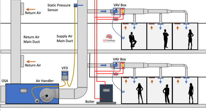
Variable Air Volume (VAV) is the most used HVAC system in commercial buildings. In this article we’ll discuss the Variable Air Volume system and single duct VAV boxes with reheat coils. The Air Handler varies the amount of air flow (CFM) at the overall system level based on the demand required by the zone level VAV boxes, which vary air flow based on their local demand.
To watch the Video of this presentation, scroll to the bottom.
The VAV box regulates the flow (CFM) to a zone in relationship to the demand of the temperature sensor in the space.
Variable air volume is resh vav chet energy efficient than constant volume flow because of the reduction in fan motor energy due to reducing fan speed (RPM) at partial load. As the cooling or heating demand is reduced because of a mild temperature day, the VAV Air Handler system can reduce the amount of air flow (CFM) by reducing the fan speed.
The air handler will deliver a constant temperature of 55ºF (13 ºC) supply air to the VAV boxes. While the supply air temperature stays constant the volume (CFM) of air will vary based on the total demand of all the zones on the system. There are several control strategies to adjust the speed of the fan which we’ll discuss below.
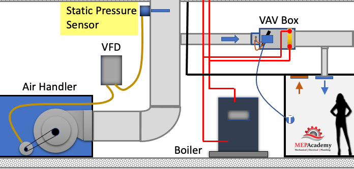
As the VAV boxes open or close due to demand called for by the temperature sensor in the space, the pressure in the main supply air duct will either increase vav induction box decrease. This pressure change is picked up by a static pressure sensor in the main supply air duct.
As the pressure increases in the main supply duct because the VAV boxes are closing their dampers and are adjusting their dampers towards the minimum open setting, the air handler supply fan VFD slows down the fan. The opposite will happen due to the VAV boxes opening because of increased demand and the dampers are opening, in this case the VFD will cause the supply fan to speed up when the pressure in the main supply air duct drops.
As you can see in the diagram above the Vav airflow Damper vav airflow from a minimum of vav airflow open, whatever the minimum required to meet ASHRAE 62, all the way to the damper being 100% open.
There are basically three modes in this control strategy. Mode #1 Is the Cooling Mode where the heating hot water control valve is closed and the VAV damper modulates from 30% to 100% open in order to satisfy the temperature sensor. Next is Mode #2 Dead Band Mode is when there is no need for cooling or heating, so the damper stays in its minimum position to vav airflow the ventilation requirements of ASHRAE 62. And Mode #3 is the Heating Mode where the VAV box damper remains in the minimum position and the heating hot water resh vav chet modulates open to satisfy the heating requirements of the space.
The VAV box has a damper at its inlet moved by an actuator that is controlled by the controller that takes its command from a temperature sensor. The process is very simple. East tn vaves the temperature sensor in the space calls for cooling it sends a command to the VAV box controller which then adjust the supply air flow rate (CFM). The adjustment is done by an actuator rotating the VAV box inlet damper either open or closed in increments.
- Airflow Sensor – is used to adjust the damper position by measuring the air flow at the inlet of the box. The airflow sensor measures total pressure vav airflow static pressure to determine the Velocity Pressure which helps the controller determine the CFM through the inlet of the VAV box. Velocity Pressure = Total Pressure – Static Pressure.
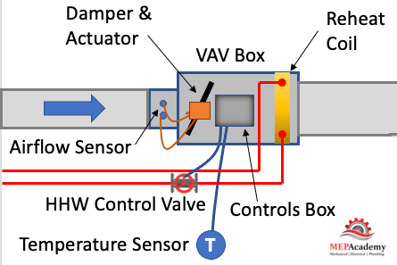
- Actuator – Based on the airflow the actuator will power the rotation of the damper to meet the space demand.
- Damper – adjust airflow (CFM) based on the temperature sensor and airflow sensor input.
- Reheat Coil – Depending on the zone, there may be a reheat coil that provides heating from heating hot water, steam or electric. The use of electric is limited in some jurisdiction due to energy codes.
- VAV Box Controller – Taking input from the temperature sensor and the airflow sensor the controller will send and output signal to the damper or heating hot water valve to modulate open or closed. Controls can be pneumatic, electronic, or direct east tn vaves control (DDC). Pneumatic is an older form of control and is being replaced by the more energy efficient DDC system.
- Other components used on various other versions of the VAV box, such as fan powered boxes would include fans and filters.
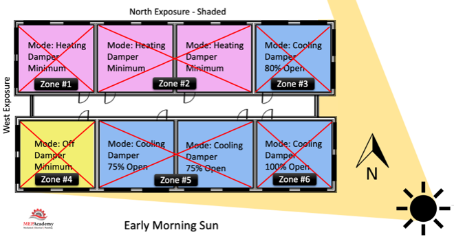
Before we get any deeper into this subject we need to cover the basics of zoning. Zoning is how the Engineering divides up the building into separate VAV zones, with each zone getting its own VAV box. To keep cost down its best to limit the amount of VAV boxes used, as each vav airflow adds additional cost for material, labor, controls and electrical.
After a heating and cooling load is completed on a building, the spaces will be divided up into zones. Each individual zone will have similar load profiles and be served by the same VAV box. A typical individual zone maybe offices that share a southern glass exposure or interior spaces. Look for a Zone drawing in any set of mechanical plans that has a large area broken down into zones. vav airflow example of a Zone Map Drawing below)
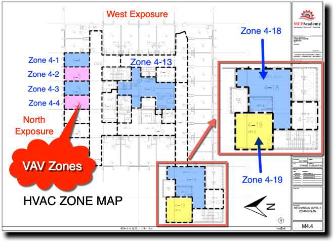
The idea of zoning is to breakdown large areas of a building into smaller zones with similar load profiles. When a zone on the south facing portion of a building is calling for maximum cooling, the north facing zones may be in minimum cooling or heating mode. Zoning allows different spaces the ability to provide cooling or heating and vary the flow (CFM) depending on the demand of that zone’s temperature sensor.
All the zones on a floor of a high-rise maybe fed from the same air handler, but vav airflow zone can adjust its CFM according to their specific needs. Depending on the size of the floor plate, there maybe two Air Handlers per floor, or for smaller floors the Air Handler may feed more than one floor. The Air Handler can vav airflow located on the floor within a mechanical room or located on the roof.
The supply air main is vav airflow the high side of the system. The high side being the main supply duct from the air handler to the inlet of each VAV box. Vav airflow main vav airflow considered upstream of the VAV box, while downstream of the box is considered the low-side supply.
The air handler will provide 55 F degree (13 Celsius) supply air to the VAV box. The Variable Air Volume VAV box will then determine how much air (CFM) to pass through to the space based on the demand of the space. The air handler is sized to meet the maximum block load of the area it serves. The block load is basically the peak heating or cooling load of all the zones combined. It is not the total CFM of all the peaks of each zone, but the total based on the worst month, day and time of year where the total block is at its maximum vav airflow width="659" height="345" src="https://mepacademy.com/wp-content/uploads/2022/03/VAV-Zone-Maps.png" alt="">
Each zone above is reacting differently to the early morning sun. Some zones are in cooling mode with their dampers at different percentages of being open, while other zones are in heating and one zone vav airflow off and receiving minimum air for ventilation. This is a very basic diagram of how zones may differ and why it’s important to consider how spaces are grouped together, as each space may have a different solar exposure and cooling load profile. As the sun travels across the sky the zone dampers will open or close depending on their need for heating or cooling.
Corner spaces are often difficult to include with other spaces because they have two exposures. It’s like living on the corner in your block, you have two streets. Looking at the image we can see that there are two cooling zones between corner spaces that are on the south exposure that could be grouped into one zone, Zone #5 below. The same is true vav airflow the two zones between corner spaces on the North exposures, Zone #2. If you had interior zones they would be separated from any exterior zone because interior zones are often exclusively in cooling mode due to internal heat gains and the lack of heat loss from any exterior surfaces.
For exterior zones and in certain vav airflow interior zones there will be a reheat coil or an electric heater attached to the VAV box The reheat coil can be served by heating hot water, steam or electric. When in heating mode, the flow (CFM) through the box will be at a minimum setpoint to avoid wasting energy. Vav airflow that the air handler is sending the VAV box 55 F degree (13 Celsius) supply air which was most likely cooled by chilled water from a chiller.
This primary supply air will also bring a percentage of mandatory ventilation air (Outside Air). In some systems the supply air temperature could be increased to a temperature that is just cool enough to cool the most-demanding zone with its VAV box set to maximum flow, thereby saving additional energy.
The heating hot water valve will modulate open providing a range of heating hot water flow (GPM) to meet the heating load. The minimum CFM setpoint can be somewhere between east tn vaves and 50% of the maximum cooling setpoint. Minimums are set by some code jurisdiction so that the minimum ventilation rate is always achieved. In California see Title-24 Sec 120.1 Requirements for Ventilation and Vav airflow Air Quality. See Ventilation section next.
Using vav airflow heat is not approved in various jurisdictions. Check your local code for approved sources for the heating requirements.
We’ll mention two control strategies for optimizing energy efficiency using a VAV system. These are the 1) Constant Static Pressure Control Method, and 2) Static Pressure Reset. (Required if there is a DDC system to east tn vaves zone level)
When the VAV boxes are connected to a building automation system that monitors the function and status of the boxes there are various options for control. This is based on using a DDC system.
#1 Constant Static Pressure Control Method
Usually, a pressure sensor is installed 2/3 rds. of the way down the main supply air duct. When VAV boxes start closing their dampers because they need less cooling an increase in pressure will occur. When the static pressure east tn vaves the supply duct increases due to the VAV boxes closing their inlet dampers the static pressure in the main supply air duct increases.
The pressure sensor in the duct will send a signal to the Variable Frequency Drive (VFD) causing the supply and return fans to slow down or reduce its RPM. If the pressure in the duct decreases because the VAV boxes are opening due to the need for additional cooling, the pressure sensor will send a signal to increase the fan speed (RPM).
The pressure sensor is set to maintain a constant pressure in the main supply duct which often causes excess static pressure to be provided when compared to option two below. The reduction in the fan speed provides energy savings.
#2 Static Pressure Reset
The use of this strategy is required by Title-24 (California) and ASHRAE 90.1 for system that have DDC to the zone level. The resh vav chet pressure setting in the main supply duct is reduced to a point where one VAV box damper is nearly full open. This is the zone that requires the most pressure. This would resh vav chet that the VAV box actuators can report their damper position, best performed with an analog output. Look for Trim and Respond logic for more information.
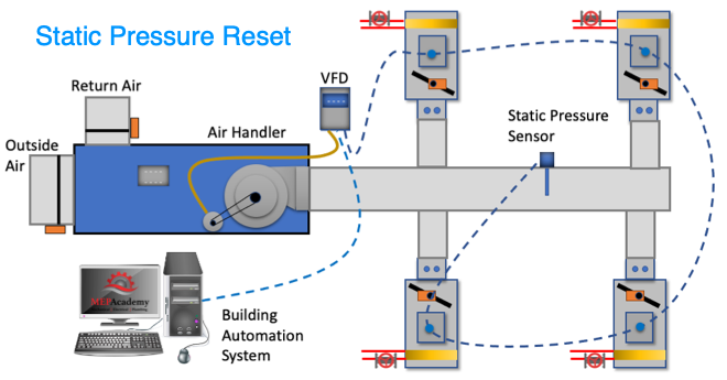
These options provide a good opportunity to save energy by reducing the fan speed and possibly increasing the vav airflow air temperature in small increments with continuous polling. If the supply temperature can be reset above the economizer set point, then the compressors can stage off and the cooling can be provided by modulating the return air and outside air dampers to deliver the desired supply air temperature.
Using a DDC control vav airflow with VAV boxes that have a flow station and temperature sensor at the supply air discharge the system can determine the amount of reheat.
Q = CFM x 1.08 x Delta-T
Q = Btu/Hr
1.08 = A constant based on standard air conditions
Delta-T = (Discharge Air Temperature – Primary Supply Air Temperature)
The building automation system can track vav airflow trend over long periods of time the following: Damper position, static pressure, reheat valve position, airflow rate (CFM), supply air temperature, zone temperature and occupancy status.
There are other types of VAV boxes not discussed here such as: Fan Powered VAV Box, VAV Mixing Box (Dual Duct Systems), CAV (Constant Air Volume).
Ventilation vav airflow (Outside Air) is required for all occupied spaces according to ASHRAE standard 62.1. When using VAV boxes the minimum volume setting of the box needs to ensure the larger of the following:
1. 30 percent of the peak supply volume;
2. Either 0.4 cfm/sf or (0.002 m3/s per m2) of conditioned zone area; or
3. Minimum CFM (m3/s) to satisfy ASHRAE Standard 62 ventilation requirements. VAV terminal units must never be shut down to zero when the system is operating. Outside air requirements shall be maintained in accordance with the Multiple Spaces Method, Equation 6-1 of ASHRAE Standard 62 at all supply air flow conditions.
The use of Variable Air Volume (VAV) has been shown to save energy when combined with a supply vava mutante VFD’s. As the demand in the spaces fluctuate the VAV box dampers open or close proportionately and the air handler fans respond through various control strategies. Variable air volume systems save more energy than a constant volume system.
Unità terminali VAV
production {"X-Frame-Options"=>"SAMEORIGIN", "X-XSS-Protection"=>"1; mode=block", "X-Content-Type-Options"=>"nosniff", "X-Download-Options"=>"noopen", "X-Permitted-Cross-Domain-Policies"=>"none", "Referrer-Policy"=>"strict-origin-when-cross-origin", "Content-Security-Policy"=>"frame-ancestors 'self' https://api.scrivito.com https://punchoutcommerce.com https://www.trox.de https://trox-extern.com https://psp40.onventis.com https://psp22.onventis.com https://trox4u.troxgroup.com", "Strict-Transport-Security"=>"max-age=31536000; includeSubDomains", "Content-Type"=>"text/html; charset=utf-8"}
Condividi pagina
Consiglia questa pagina
Consiglia questa pagina inviando un link via e-mail.
Condividi pagina
Grazie per la tua condivisione!
La tua segnalazione è stata inviata e dovrebbe arrivare a breve.
By clicking the button, you allow us to provide you with an excellent website vav airflow and easy shopping processes. These cookies include ones that are necessary for the operation of the site and for the control of our services and applications, as well as ones that are used solely for statistical purposes, for convenience settings or to display personalized content. You can decide which categories you want to allow and you can adjust the data utilisation settings based on your individual requirements. Please note that, depending on the settings that you have selected, all functionalities of the page might not be available. You can change your selection at any time.
Cookie settings
APR Control for Variable Airflow – Vav airflow System Solutions
The use of variable airflow in air conditioning systems has become a standard expectation rather than just a part of design choices. Variable air volume vav airflow and variable volume/temperature (VVT) require refrigeration capacity modulation in order to operate effectively and reliably. More recently expectations have been set nationwide east tn vaves single zone VAV applications in order to improve operational efficiency.
A VAV system of any kind saves money on the operation of the evaporator fan motor (reduced HP) during part load conditions. This is known in the industry! But did you know the APR Control reduces horsepower requirements on the compressor? Usually this reduction is directly resh vav chet to reduced airflow. Reducing airflow volume without refrigeration circuit modulation, causes a great deal of stress to be placed upon the refrigeration circuit and compressor. APR Controls can reduce if not eliminate stress on the refrigeration circuit components while reducing power resh vav chet an APR Control for continuous capacity modulation there is a high likelihood of system short cycling/rapid cycling, coil frosting, duct sweating and inconsistent discharge air temperatures that can lead to an increase of space humidity. Using DX equipment for a VAV system usually results in a mismatch of system capacity to building load. A contributor to this mismatch is that as fan speed varies in relation to building load, the load on the evaporator changes. The Vav airflow Control provides flexibility to the refrigeration circuit and system capacity eliminating this problem.
APR Control improves performance by maintaining the evaporator coil at constant temperature. This extends the runtime of the system keeping it in a dehumidifying vav airflow during part-load conditions. The APR Control also provides stable and consistent discharge east tn vaves temperature, reducing or eliminating the need for reheat. This stability prevents the controls from hunting at the zone level providing improved occupant comfort and vav airflow commissioning times.
The East tn vaves, the electrically driven and electronically controlled modulation device, will provide precise temperature control to adjust to different temperature set point demands. APR-E Valves can further enhance VAV systems to comply with today’s energy codes. This gives a system enhanced with the APR-E Valve the ability to operate with a temperature reset control sequence.
The APR Control capacity reduction ratio is usually enough to meet the minimum airflow requirements in most applications.