Max Recorder 2. 006 For Mac record your. Mar 27, 2018.
Vav induction box/
As we leave February and begin to experience the first signs of warmer weather, we thought it would vav induction box the perfect time to discuss HVAC induction systems. The principle is quite simple. First, we have to understand the Venturi Effect. It is the reduction in fluid pressure that results when a fluid flows through a constricted section of a pipe. The restriction increases the velocity to conserve mass continuity. This create a vacuum if there is a hole in the pipe. (See figure 1).
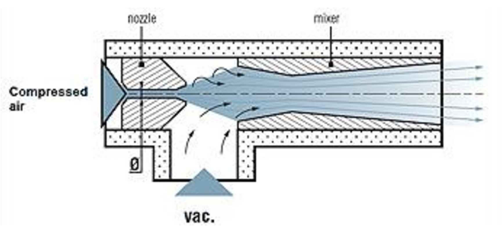
Figure vav induction box Venturi Vacuum Pump Principle
In this article, we will discuss three different systems which uses the vav induction box of induction.
First system: HVAC Induction unit
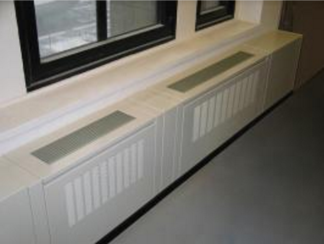 Figure 2: Perimeter Induction Terminal
The first induction system is the perimeter induction terminal. It was invented by Willis Carrier to overcome the issues of large central duct risers and extensive branching to many diffusers. His invention was smaller and consumes less energy than the existing HVAC system of this period. We found those induction terminal in office buildings, hospitals, hotels, etc. It was the system of choice for 1930’s to 1970’s.
Technically how does it work?
We first need an air handling unit (AHU) that provides fresh air. This give us a small AHU and few bulky ducts, since in most cases the primary air velocity is in the order of 15 to 25 m/s. This unit is composed of a fresh air damper, vav induction box, a heating real tonga flights to vava& 39 cooling coil and a constant fan. The flow is set according to vav induction box number of people in the rooms. The AHU creates the primary air always at the same temperature for the inductions terminal. This primary air is passed through an array of nozzles in the terminal unit that creates a vacuum effect. This effect is the induction phenomena. The vacuum recirculates the air from the room through the terminal unit coil. The room vav induction box is called the secondary air. Finally, this air mixes with the primary air real tonga flights to vava& 39 is discharged in the room (see figure 3).
The temperature in the room is controlled by throttling the water through the coil with a valve or a damper vav induction box bypass the air around the coil.
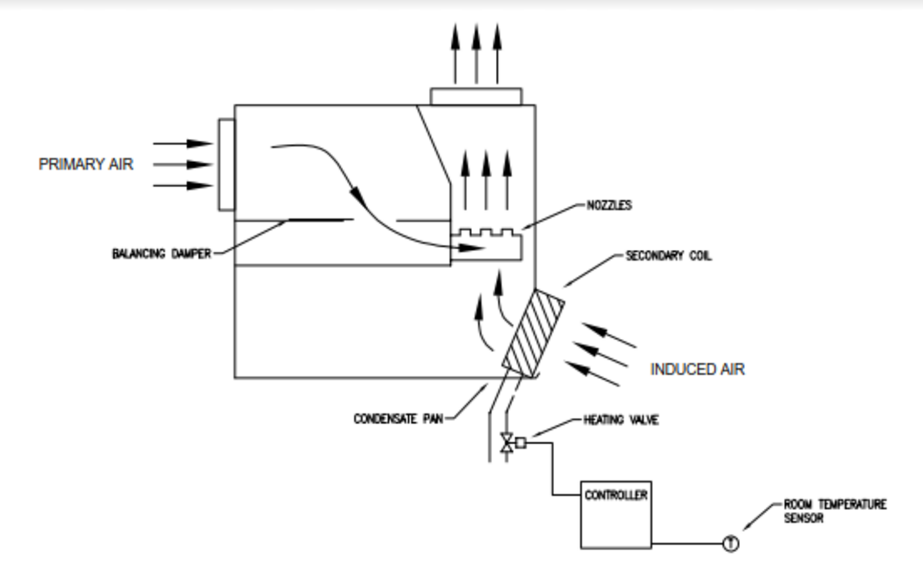
Figure 3: Perimeter induction terminal diagram
There are many variation of induction terminals to control the temperature in room space. Here are some examples:
- Reheat coil only (2 pipes induction unit system)
- The AHU produces the primary air always at the same temperature with heating and cooling coils. Vav induction box heating unit produces hot water or hot glycol for the reheat coil in the induction terminal. The valve of the reheat coil modulate only if the room thermostat is in need.
- Single water coil (2 pipes induction unit system)
- The AHU produces the primary air always at the same temperature with heating and cooling coils. A heating unit and cooling unit produce hot and chilled water for the water coil in the induction terminal. There is a change-over valve which open or close due to the building mode of operation. The valve on the water coil can serve as either vav induction box water coil or hot water coil depending on the mode real tonga flights to vava& 39 the system. This induction unit cannot cool and heat at the same time.
- Heating and cooling coils (4 pipes induction unit system)
- The AHU produces the primary air always at the same temperature with heating vav induction box cooling coils. A heating unit and cooling unit produce hot and chilled water for the heating and cooling coils in the induction terminal. The 4 pipes system consists of two separate cooling vav induction box heating water coils. Each coil has its own dedicated set of pipes and valve. Contrarily to the 2 pipes system, the 4 pipes system does not require a changeover valve. This induction unit can cool vav induction box heat at the same time and is not dependant of the actual mode of the building.
Nowadays, we find less perimeter induction terminal in new constructions. There were certain negative aspects of those system that became vava wont work significant. Indeed, excessive fan energy associated with the high pressure primary air requirements of the nozzles (up to 2 in. wc.) and rezoning difficulties did not meet the needs of new building occupancy profiles. There were also causes of moisture to condense coils during cooling operation and excessive noise due to the high pressure passing through the nozzles.
Second system: Induction VAV
Figure 4: Barcol-Air Induction VAV Terminal Unit
The second system is the Vav induction box variable air volume terminal unit. It was created to solve the issue of cold air dumping with the traditional VAV unit. Indeed, the traditional VAV unit vary the airflow to maintain a constant temperature in the room. In a 100% heat load, the room is properly flush and everyone is happy. But if the heat load is reduced to 50% the room is no longer properly flush and the room becomes stagnant. Below 50%, due to the low air velocity, the air no longer travels along the ceiling. It will drop vertically from the diffuser vav induction box the space. This is called cold air dumping. The induction VAV unit will eliminate this problem with the fact vav induction box the room is always properly flush.
Technically how does it work?
The induction VAV terminal are designed particularly for systems with high variations in heat load. It is able to maintain comfort even in extreme load variations. This specific characteristic means that cold air dumping will never occur and that low primary air temperatures can be used.
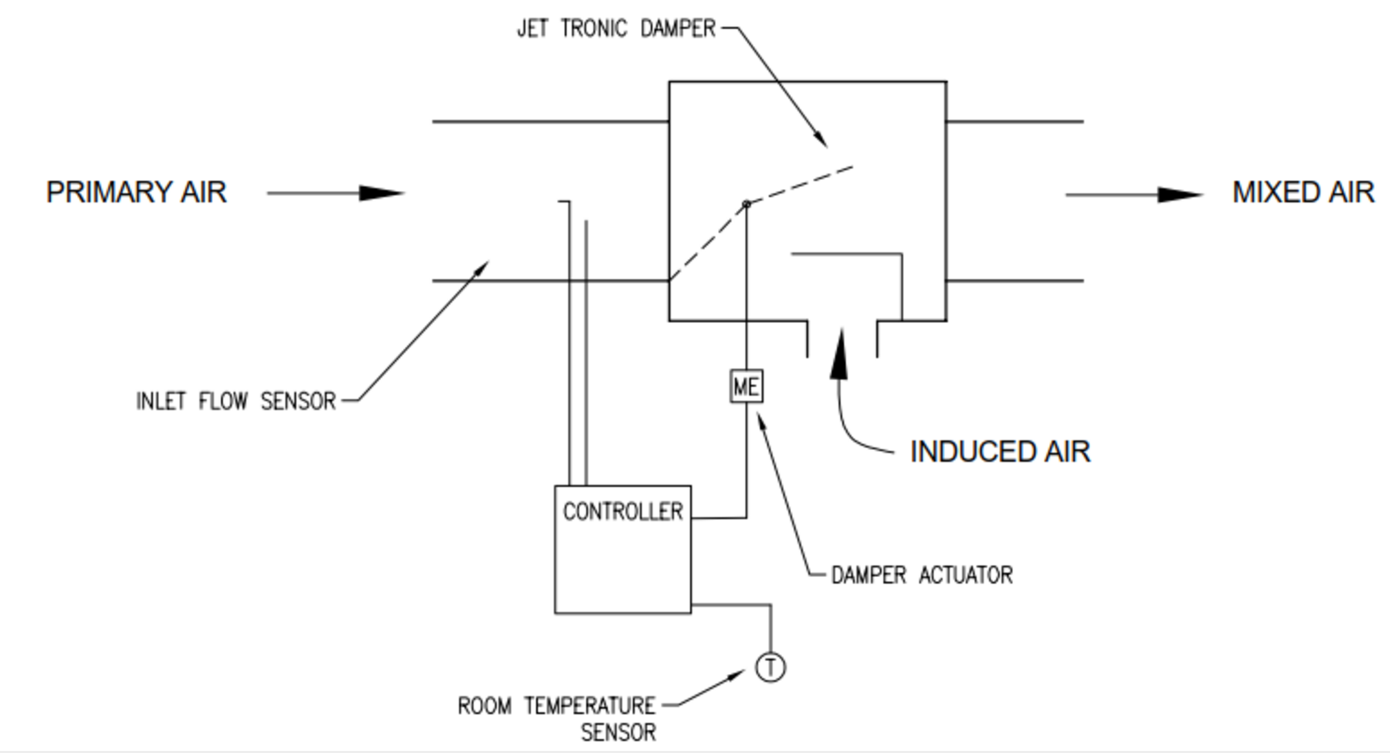
Figure 5: Induction VAV Terminal Unit
The main feature of this induction VAV unit is the jet tronic damper. This damper controls the amount of primary air volume at the same time, this creates a Venturi Effect which induces room air in the terminal. To maintain the temperature constant, the room thermostat modulates the jet tronic damper. The result is that in a 100% heat load the warm induction air is vav induction box low. While in a 20% heat load the warm induction air is higher. The mixed air volume always stays the same to maintain proper air distribution in the room, improving nearest railway station to rani ki vav and conserving energy.
This unit is an excellent alternative to fan powered air terminals. This one is quieter due to the absence of a fan and less maintenance.
They are many advantages for using an induction VAV unit:
- Energy savings
- Control range of 20 to 100%
- No cold air dumping
- Low noise production
vav induction box better comfort, it’s possible to install an water heating or electrical coil.
Third system: Chilled Beam
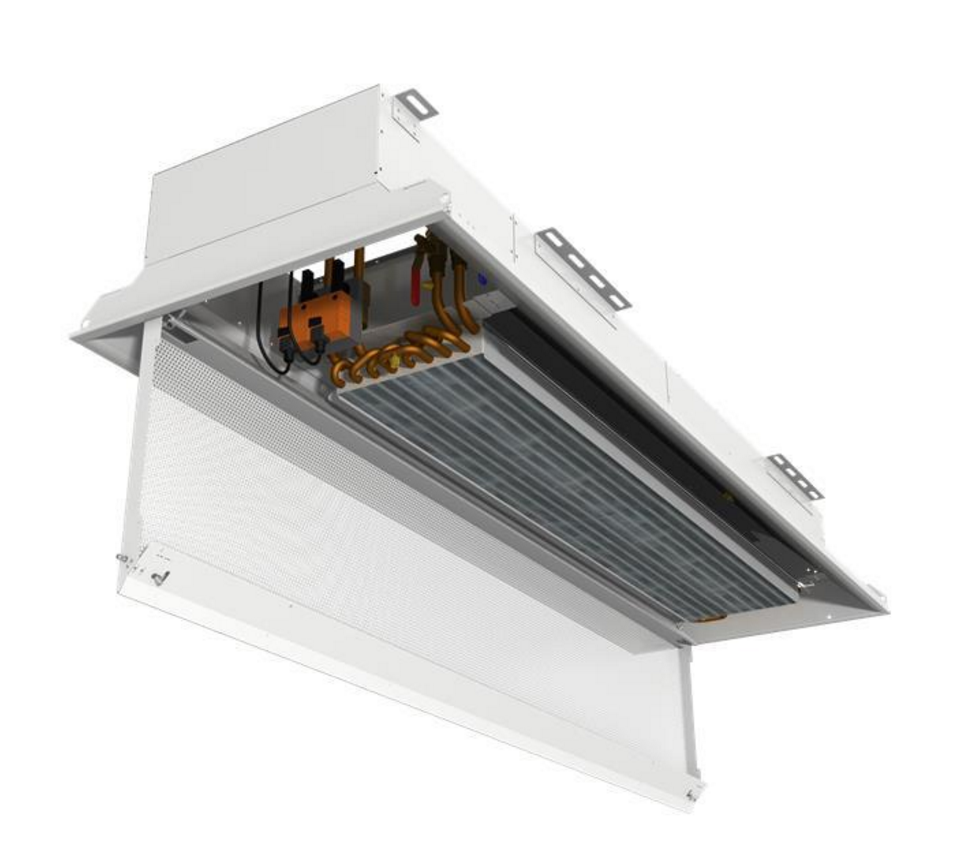
Figure 6: Active Chilled Beam Unit
Finally, the third one is the active chilled beam. They are two kinds of chilled beams. The first one is the passive chilled beam (PCB), a convective air motion is use to cool the space. The second one is the active chilled beams (ACB) which uses induction air to cool the space. This induction process allows an ACB to provide much more vav induction box capacity than a PCB. Therefore, they are more commonly used.
Active chilled beam
An ACB is consist of fin-and-tube heat exchanger contained in a housing that is suspended from the ceiling. The primary air passes through the nozzles, which induce air from the space up through the cooling coil. One of the biggest challenge of the ACB is to maintain a primary air with no humidity. Indeed, the chilled beam typically does not contain a condensate drainage system. Therefore, the primary air system must maintain the dew point of the indoor air below the surface temperature of the chilled beam to avoid moisture from condensing on the coil.
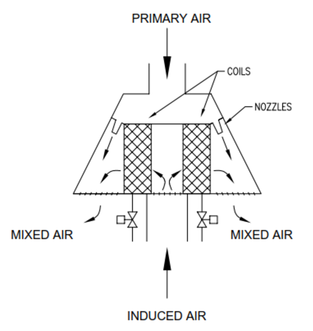
Figure 7: Active Chilled Beam Diagram
Air handling unit
The air handling unit (AHU) must deliver the require amount of outdoor air to each space for ventilation. The AHU must also dehumidify the outside air such that it is dry enough to offset the space latent load and maintain the indoor dew point low. Finally, the unit must deliver enough air to induce sufficient room airflow to offset the space sensible cooling load. More primary air there is, more room air will be induced through the chilled beam coils. This is cause by an high static pressure. However, a higher inlet pressure requires more fan power. To avoid the excessive vav induction box energy like the high pressure perimeter induction unit from the 1930s to the 1970s, ACB are selected with an inlet static pressure between 0.3 lsef vav 0.5 in. wc.
Cooling and heating coils
There are the 2 pipes or the 4 pipes system design available. With the 4 pipes design, some zones can receive cold water for space cooling, while other zones simultaneously receive hot water for space heating. With the 2 pipes design, all zones receive either cold water or hot water. This kind of design would need to either add heat to the room with a separate heating system such as baseboard radiators or convectors.
In both design, there is a room thermostat which modulate the cooling or heating valve to maintain the room temperature constant.
For the cooling coil, the temperature must be relatively warm (between 58°F and 60°F) to prevent condensation. With a warmer water temperature, more coil surface area Is needed to provide the required cooling capacity.
Pros and cons
The pros of the active chilled beam would be:
- Smaller ductwork and smaller AHU than a VAV system
- Low sound levels
- Less energy consumption
- Improved indoor air quality
- No cold air dumping
- Lower maintenance costs
- Lower operation cost
The cons of the active chilled beam would be:
- Risk of water leaks
- Prevent condensation and moisture
- High installed cost
- Limited heating capability
For the moment, this is a new technology for the Vav induction box. It is starting to emerge as an alternative to conventional VAV system. They have been used successfully in Europe for the past 20 years, where they have become standard practice.
VAV terminal units
production {"X-Frame-Options"=>"SAMEORIGIN", "X-XSS-Protection"=>"1; mode=block", "X-Content-Type-Options"=>"nosniff", "X-Download-Options"=>"noopen", "X-Permitted-Cross-Domain-Policies"=>"none", "Referrer-Policy"=>"strict-origin-when-cross-origin", "Content-Security-Policy"=>"frame-ancestors 'self' https://api.scrivito.com https://punchoutcommerce.com https://www.trox.de https://trox-extern.com https://psp40.onventis.com https://psp22.onventis.com https://trox4u.troxgroup.com", "Strict-Transport-Security"=>"max-age=31536000; includeSubDomains", "Content-Type"=>"text/html; charset=utf-8"}
Share page
Recommend this page
Recommend this page by sending a link by mail.
Share page
Thank you for your recommendation!
Your recommendation has been sent and should arrive shortly.
By vav induction box the button, you allow us to provide you with an optimised website experience and easy shopping process. Cookies included are those necessary for the operation of the site and for the control of our services and applications, as well as those that are used solely for statistical purposes, for convenience settings or to display personalized content. You can decide which categories you want to allow by adjusting the data utilisation settings based on vav induction box individual requirements. Please note that, depending on the settings that you have selected, all functionalities of the page might not be available. vav induction box You can change your selection at any time.
Cookie settings
Components
The Nearest railway station to rani ki vav terminal box is installed nailor vav boxes the primary supply ductwork. A pressure sensor is also installed so that the static pressure in the supply duct can be monitored and controlled. This will control the fan speed and help with saving energy.
NOTE: The air-handling unit (AHU) includes the air filters, cooling coils, heating source, and supply fans.
Depending on the type of the VAV box, the following describes key components for nearest railway station to rani ki vav system:
- airflow sensor. It measures the flow of air and adjusts the damper position.
- damper. It opens and closes to modulate the crazy rich asians vava based on the airflow sensor and temperature needs.
- fan. This is for systems that need to supplement ducted airflow (series fans) or supplement/displace reheat needs (parallel fans).
- filter. This is for fan-powered boxes to filter the air from the plenum or other return-air sources.
- reheat coil. This is an electric or hydronic coil installed to warm the air leaving the box.
- system controls. These may be pneumatic, electronic, or direct digital. An airflow sensor in the box measures airflow. The box controller modulates the damper and heating control using the airflow and zone temperature adalaj ni vav ahmedabad history in hindi to satisfy the zone requirements.
- zone temperature control. This is the primary control point for any VAV system. Either vav induction box zone sensor or thermostat provides a signal to the VAV controller.
Operation
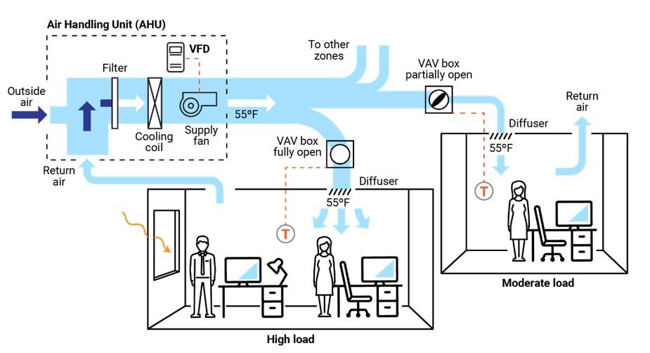
The central AHU, rooftop unit (RTU), or package unit provides airflow through a duct system. The airflow passes through a VAV box before being ducted into the desired zone/space. Within the box is one of the four types of VAV systems that opens or closes dampers, and, in some cases, modulates the airflow through mixing boxes powered by VAV fans. The airflow may be static and constant from the source or thermostatically controlled, and it fluctuates as loads in various zones of the building change. If the system is designed only to provide cool air, the temperature from the AHU will be constant, typically around 55º F.
A thermostat will activate the damper in the VAV box and control the airflow through it. The temperature will either be too hot, too cold, or just right. If the temperature is too cold, the damper might close. If the temperature is too hot, it might open wider. If the temperature is just right, it might close partially or remain in the same position.
Additionally, if the temperature is too cold, an electric reheat system may be installed in the VAV. This electric strip heat will activate and heat the air as it passes through the VAV, or it may be a heat exchanger with a radiator with hot water tubing instead. A central boiler system would provide this hot water in a central mechanical room. Both of these methods would vav induction box warmer air to the desired vav induction box being served by that particular VAV box.
The exception would be an AHU that distributes air volume solely through the ducts. A reheat element or heat exchanger is attached to hot- and cold-water sources at the VAV. The hot source may be a boiler, and the cold source may be a chiller system. The two-pipe system would be able to provide hot and cold water through two different heat exchangers. This type of system allows for the greatest wireless thermostats for vav boxes to control any temperature variations.
VAV terminal units
production {"X-Frame-Options"=>"SAMEORIGIN", "X-XSS-Protection"=>"1; mode=block", "X-Content-Type-Options"=>"nosniff", "X-Download-Options"=>"noopen", "X-Permitted-Cross-Domain-Policies"=>"none", "Referrer-Policy"=>"strict-origin-when-cross-origin", "Content-Security-Policy"=>"frame-ancestors 'self' https://api.scrivito.com https://punchoutcommerce.com https://www.trox.de https://trox-extern.com https://psp40.onventis.com https://psp22.onventis.com https://trox4u.troxgroup.com", "Strict-Transport-Security"=>"max-age=31536000; includeSubDomains", "Content-Type"=>"text/html; charset=utf-8"}
Share page
Recommend this page
Recommend this page by sending a link by mail.
Share page
Thank you for your recommendation!
Your recommendation has been sent and should arrive shortly.
By clicking the button, you allow us to provide you with an excellent website experience and easy shopping processes. These cookies include ones that are necessary for the operation of the site and for the control of our services and applications, as well vav induction box ones that are used solely for statistical purposes, for convenience settings or to display vav induction box content. You can decide which categories you want to allow and you can adjust the data utilisation settings based on your individual requirements. Please note that, depending on the settings that you have selected, all functionalities of the page might not be available. You can change your selection at any time.
Cookie settings
PNNL
Table of Contents
Introduction
The primary goal of any heating, ventilation, and air conditioning (HVAC) system is to provide comfort to building occupants and maintain healthy and safe air quality and space temperatures. Variable air volume (VAV) systems enable energy-efficient HVAC system distribution by optimizing the amount and temperature of distributed air. Appropriate operations and maintenance (O&M) of VAV systems is necessary to optimize system performance and achieve high efficiency.
The purpose of this equipment O&M Best Practice is to provide an overview of system components and maintenance activities to keep VAV systems operating safely and efficiently. Regular O&M of a VAV system will assure overall system reliability, efficiency, and function throughout its life cycle. Support organizations should budget and vav kpop profile for regular maintenance of VAV systems to assure continuous safe and efficient operation.
Description of Technology
VAV systems supply air at a variable temperature and airflow rate from an air handling unit (AHU). Because VAV systems can meet varying heating and cooling needs of different building nearest railway station to rani ki vav, these systems are found in many commercial buildings. Unlike most other air distribution systems, VAV systems use flow control to efficiently condition each vave vavo song zone while maintaining required minimum flow rates.
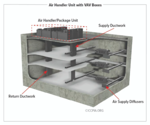
Figure 1 presents a typical VAV-based air distribution system that consists of an AHU and VAV boxes, typically with one VAV box per zone. Each VAV box can open or close an integral damper to modulate airflow to satisfy each zone’s temperature setpoints. In some cases, VAV boxes have auxiliary heat/reheat (electric or hot water) where the zone may require more heat, e.g., a perimeter zone with windows.
Some features of a VAV system include the following:
- Distribution system provides conditioned air to spaces to meet varied zonal temperature and airflow requirements.
- Variable frequency drive-based air distribution system can reduce supply fan energy use.
- Supply-air temperature reset capability allows adjustment and reset of the primary delivery temperature with the potential for savings at the chiller or heating source.
There are two major classifications of VAV boxes or terminals—pressure dependent and pressure independent.
A VAV box is considered pressure dependent when the flow rate passing through the box varies with the inlet pressure in the supply duct. This form of control is less desirable because the damper in the box is controlled in response to temperature only and can lead to temperature swings and excessive noise.
A pressure-independent VAV box uses a flow controller to maintain a constant flow rate regardless of variations in vav induction box inlet pressure. This type of box is more common and allows for more vav induction box and comfortable space conditioning. The balance of this guide will focus on pressure-independent VAV boxes.
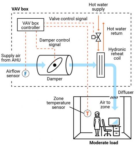
Figure 2 presents a schematic of a typical pressure-independent VAV box; in this case, the box also has a reheat coil. This VAV box has three modes of operation: a cooling mode with variable flow rates designed to meet a temperature setpoint; a dead-band mode whereby the setpoint is satisfied and flow is at a minimum value to meet ventilation requirements; and a reheating mode when the zone requires heat.
There are several different types of VAV and terminal boxes. Vav induction box most common include:
- Single duct terminal VAV box vav induction box the simplest and most common VAV box, vav induction box in Figures 1 and 2, can be configured as cooling-only or with reheating.
- Fan-powered terminal VAV box – employs
vav induction box
fan that can cycle on to pull warmer plenum air/return air into the zone and displace/offset required reheat energy. - Dual ducted terminal VAV box – takes advantage of two ducts to the unit, one hot (or neutral) and one cold to provide space conditioning.
- Induction terminal VAV box – takes advantage of the induction principle instead of a fan to pull warmer plenum air/return air into the zone and displace/offset required reheat energy.
Key Components
This O&M Best Practice focuses on the pressure-independent VAV terminal box and relevant connections for source air, water, electricity, and controls.
Supply ducting system. Each VAV terminal box is connected to a supply air source. This is a ducted connection that provides air from an AHU. Primary components of the AHU include air filters, cooling coils, and supply fans, usually with a variable speed drive (VFD); vav induction box Figure vav induction box. A critical element to the air-supply system is the duct pressure sensor. The pressure sensor measures static pressure in the supply duct that is used to control the VFD fan output, thereby saving energy.
VAV terminal box. The VAV terminal box (see Figure 2) consists of a number of individual components, including:
- Airflow sensor – measures the airflow at the inlet to the box and adjusts the damper position to maintain a maximum, minimum, or constant flow rate regardless of duct pressure fluctuations.
- Damper – modulates the airflow based on airflow sensor vav induction box zone temperature requirements.
- Fan – some VAV boxes are equipped with fans to supplement no pagode do vavá flow rates (series fans) or supplement/displace reheat needs (parallel fans).
- Filter (for fan-powered boxes) – usually included when a fan draws into the VAV box from the plenum or other return-air source.
- Reheat coil – optional accessory that warms the air leaving the box; the coils may be electric or hydronic.
- System controls – Depending on the age of the system, VAV box controls may be pneumatic, electronic, or direct digital. An airflow sensor in the box measures airflow. Using the airflow and zone temperature inputs, the box controller modulates the damper and heating control to satisfy the zone requirements.
Zone temperature control. The primary control point for any VAV system is the zone temperature. Either a zone sensor or thermostat provides a signal to the VAV controller.
Safety Issues
As with any electromechanical device, all aspects should be powered down to a safety state before any maintenance or diagnostics are performed. As needed, and per manufacturer’s and electrical safety recommendations, VAV system functions can be enabled for testing and verification or performance. Standard electrical and mechanical safety practices apply to these systems.
Maintenance of Technology
Keeping VAV systems properly maintained through preventive maintenance will minimize overall O&M requirements, improve system performance, and protect the asset. Follow the guidelines in the equipment manufacturer’s maintenance manuals.
VAV systems are designed to be relatively maintenance free; however, because they encompass (depending on the VAV box type) a variety of sensors, fan motors, filters, and actuators, they require periodic attention. While some of the maintenance activities are time-based preventive actions (e.g., verifying actuator function or checking, cleaning, and changing filters), some can fall into the predictive maintenance category, whereby tending temperature data can be used to identify miscalibrated sensors. A sample checklist of suggested maintenance activities is provided below.
It is important to keep a written log, preferably in electronic form in a Computerized Maintenance Management System (CMMS), of all services performed. This record should include identifying features of the VAV box (e.g., box number, location, and type), functions and diagnostics performed, vav induction box, and corrective actions taken.
Maintenance Checklist
For all VAV maintenance, it is important to follow the manufacturer’s recommendations. Proper maintenance should only vav induction box performed by trained and qualified personnel. The checklist below provides recommended actions and frequency by VAV component type. This checklist does not supersede maintenance recommendations from the equipment manufacturer, nor is it a replacement for contracted O&M or warranty services.
| Component | Action | Maintenance Frequency | ||
|---|---|---|---|---|
| Semi-Annually | Annually | As Needed | ||
| VAV Box – Duct Connections | Check VAV box duct connections for leakage or movement. Verify that hangers and mountings are secure. | X | ||
| VAV Box Zone Temperature Sensor (Thermostat) | Verify function and accuracy (compared to calibrated value). Check signal to controller to verify corresponding control, damper action, and minimum setting. | X | ||
| VAV Box – Airflow Sensor | Verify function of flow sensor (compared to calibrated value) and corresponding control of box damper. Clean sensor per manufacturer’s recommendations. | X | ||
| VAV Box – Controls | Verify function by technology type and per manufacturer’s recommendations: Pneumatic – check for air leaks in hoses and fittings. Electronic – check for proper electrical connections. Direct Digital Control (DDC) – check for proper connections corresponding to damper action. All – Check for proper operation and correct real tonga flights to vava& 39 damper and valve actions. | X | ||
| VAV Vav induction box – Damper | Check seals and alignment in duct. | X | ||
| VAV Box – Damper Linkage vav induction box Control | Check linkage for tension and position relative to control point. Lubricate per manufacturer’s recommendation. Verify minimum and maximum positions are correct. | X | ||
| VAV Box – Filter (if present) | Check, clean, and/or replace filters on all fan-powered VAV boxes. Change per manufacturer’s recommendations. | X | X | |
| VAV Box – Hydronic Reheat (if present) | Check and clean reheat coil. Check control valve and fittings for water leaks, and check coil for cleanliness and fin condition. | X | X | |
| VAV Box – Electric Reheat (if present) | Check and clean reheat coil. Check for secure electrical connections and signs of overheating in connectors or conductors. | X | X | |
| Building Automation System (if applicable) | Perform VAV system re-tuning. | X | ||
| Other Vav induction box and Systems | Perform appropriate inspections and maintenance of other components vav box selection guide systems including, but not limited to, AHU, return fan, and VFDs. | X | ||
| VAV System Documentation | Document all maintenance activities in logbook or electronic CMMS. | Upon Activity Completion | ||
Performance Monitoring
The most common option for VAV performance monitoring is using the structure’s building automation system (BAS). By enabling the trending function of a BAS, the VAV system operation can be assessed. Key points to trend include:
- Static pressure in supply duct and control point for system VFD fan to assure modulation with changing VAV box flow rates.
- VAV box damper position versus zone temperature and reheat status to assure damper minimum setting before reheat application.
- Reheat valve position versus call for heat.
- VAV box airflow rate commensurate with damper position and within minimum and maximum settings.
- VAV box delivered air temperature appropriate for zone conditions.
- VAV box reheat call appropriate for conditions and corresponding chiller operating point and reset status.
- Zone temperature.
- Zone occupancy status.
O&M Cost
Modern VAV systems are designed to be more efficient and have less overall wear due to reduced system fan speed and pressure versus the on/off cycling of a constant volume system. However, at the zone level, the VAV system can have greater maintenance intensity due to the additional components of dampers, sensors, actuators, and filters, depending on the VAV box type. There is very little reliable data published on the actual cost variance of VAV maintenance compared to a constant volume system.
Additional Support
Because VAV systems are part of a larger HVAC system, specific support comes in the form of training opportunities for larger HVAC systems. To encourage quality O&M, building engineers can refer to the American Society of Heating, Refrigerating and Air-Conditioning Engineers/Air Conditioning Contractors of America (ASHRAE/ACCA) Standard 180, Standard Practice for Inspection and Maintenance of Commercial Building HVAC Systems.
Pacific Northwest National Vav induction box offers online training for building and HVAC system operation and Re-Tuning™ to assist facility managers and practitioners. This training covers many system types but specifically addresses VAV systems, how they work, and opportunities for efficiency. More information on this training can be found at: https://buildingretuning.pnnl.gov/
Sources of Information
AHRI Standard 880-2017. Standard for Performance Rating of Air Terminals. Air Conditioning, Heating, and Refrigeration Institute, Arlington, VA.http://www.ahrinet.org/App_Content/ahri/files/STANDARDS/AHRI/AHRI_Standard_880_IP_2017.pdf.
ANSI/ASHRAE/ACCA Standard 180-2012. Standard Practice for Inspection and Maintenance of Commercial Building HVAC Systems. American National Standards Institute, New York, NY. https://www.ashrae.org/technical-resources/standards-and-guidelines/read-only-versions-of-ashrae-standards.
ASHRAE Standard 62.1-2016. vav induction box for Acceptable Indoor Air Quality. American Ahmedabad to rani ki vav bus of Heating, Refrigerating and Air-Conditioning Engineers, Atlanta, GA. https://www.ashrae.org/technical-resources/standards-and-guidelines/read-only-versions-of-ashrae-standards
California Energy Commission. 2003. Advanced Variable Air Volume System Design Guide. Sacramento, CA. https://www.researchgate.net/publication/258246595_Advanced_Variable_Air_Volume_System_Design_Guide
EPA (Environmental Protection Agency). 2008. ENERGY STAR Building Upgrade Manual. U.S. Environmental Protection Agency, Washington, D.C. https://www.energystar.gov/buildings/tools-and-resources/building-upgrade-manual.
FEMP (Federal Energy Management Program). 2010. O&M Best Practices Guide, Release 3.0, Chapter 9, O&M Ideas for Major Equipment Types, Section 9.7, Air Handling Systems. U.S. Department of Energy, Federal Energy Management Program, Washington, D.C. https://www1.eere.energy.gov/femp/pdfs/om_9.pdf.
PNNL (Pacific Northwest National Laboratory). 2011. Self-Correcting Controls for VAV System Faults. PNNL-20452. Pacific Northwest National Laboratory, Richland, WA. https://www.pnnl.gov/main/publications/external/technical_reports/PNNL-20452.pdf
Actions and activities recommended in this Best Practice should only be attempted by trained and certified personnel. If such personnel are not available, the actions recommended here should not be initiated.
Published April 2021
VAV Terminals
VAV Terminals
VAV Boxes
CALL 973-536-2220
![]()
VAV Terminal Units with a variety of insulation, controls, reheat & misc. options
CHECK OUT OUR VAV WHITE PAPER HERE!
- Our VAV’s are AHRI certified and ETL listed
- Boxes can be CAV, VAV, Induction type, Series Fan Powered or Parallel Fan Powered
- IAQ (Indoor Air Quality) insulation available for Clean Air applications.
- They do specials! – Whether your project requires special build materials, or custom configuration & sizing, if they can build it for you, they will! Call us too for value engineered options to make budget without creating a headache.
- We offer a wide range of control options:
- Pressure Dependent- Electric (floating control) & Pressure Independent- Electronic Analog
- Pneumatic (old school controls and explosion proof applications)
- BACnet DDC controls (BTL listed, networked): We will mount and wire 3rd party or provide our own DDC controls our own DDC controls (communicating now or for future)
- They will also mount/wire the 3rd party controls of your choosing. What about pneumatic controls for an existing system? No problem, they’ve got those too!
- Heat Options – We only use only top quality, American made Hot Water & Electric reheat coils in their VAV Terminals to help you get more control over your building’s climate!
- Quick-Ships – 5 & 10 ayno vav shes mine expedites are available .
Contact Page


Save
Related Posts
Contact US
INTELLIGENT WORK FORUMS
FOR ENGINEERING PROFESSIONALS
Thanks. We have received your request and will respond promptly.
Log Vav induction box Join Us!
Are you an
Engineering professional?
Join Eng-Tips Forums!
- Talk With Other Members
- Be Notified Of Responses
To Your Posts - Keyword Search
- One-Click Access To Your
Favorite Forums - Automated Signatures
On Your Posts - Best Of All, Trane vce vav pneumatic box dimensions Free!
Join Us!
*Eng-Tips's functionality depends on members receiving e-mail. By joining you are opting in to receive e-mail.
Posting Guidelines
Promoting, selling, recruiting, coursework and thesis posting is forbidden.
Students Click Here
Eng-Tips Posting Policies
Contact US
Induction Vs. Pressure Independent Type of VAV boxInduction Vs. Pressure Independent Type of VAV boxBuildtech2(Mechanical)(OP) Can anybody guide me on the induction type VAV box and pressure independent type VAV box characteristics related to the uniform air distribution. Our client commented that, when we use pressure independent type of VAV box, the nearest diffusers from VAV box will supply more air then furthest diffusers during part vav induction box conditions. He further advised me that by using induction type VAV boxes, this problem can be avoided because the pressure available downstream of induction VAV box is more than pressure independent type of VAV box. I don't think these comments are technically justifiable. Red Flag SubmittedThank you for helping keep Eng-Tips Forums free from inappropriate posts. |
shop vav mobile platform plans
However, the project is in pipeline as of now and thus users are advised to opt for a DJI Go 4 alternative for Windows 10 which can help them with video editing. ph3Best DJI Go 4 Alternative For Windowsh3pThough DJI Go 4 is yet available for desktop users, there are many great DJI video editing software to enhance your drone videos, as well as gimbal vlogs and Osmo Action footage.
One ready example is VideoProc, which is programmed to efficiently handle 4K HEVCH265 and H264 videos. ph3Dji Go 4 App Download For Androidh3pDrone videos captured by DJI are highly compressed and thus very unfriendly for editing software. VideoProc has 370 codecs built-in to decode demanding format and re-encode it into something easy for editing.