Png"If you dont want to have your older archive file(s) connected to Outlook all the time, you can close it via the Data Files tab of your Account Settings dialog. polliOpen the Data Files management tab.
ulliOutlook 2007brFile-gt; Data File ManagementliliOutlook 2010 2013 2016 2019 Office 365brFile-gt; Account Settings-gt; Account Settings…-gt; tab: Data FilesliulliliSelect the archive pst-file you wish to disconnect.
How to flow hood tab on vav systems/
How to Perform and Document TAB on HVAC Systems
 What is TAB of HVAC systems
Testing, Adjusting, and Balancing (TAB) is a critical process in the realm of HVAC (Heating, Ventilation, and Air Conditioning) systems. TAB is the systematic and methodical evaluation of these systems to ensure they operate efficiently, effectively, and as designed. The primary goal of TAB is to create a balanced and harmonious environment where indoor how to flow hood tab on vav systems quality, thermal comfort, and energy efficiency are optimized.
The TAB process involves a series of tasks, including measuring and adjusting variables such as air and water flow rates, temperature differentials, and pressure levels. Technicians utilize various instruments and tools to obtain accurate data and then make adjustments to HVAC system components like dampers, valves, and fans. The objective is to align the system's performance with the how to flow hood tab on vav systems specifications and intended functionality
how to flow hood tab on vav systems vave vavachi song mp3 download Proper TAB provides several benefits, including reduced energy consumption, enhanced occupant comfort, and prolonged equipment life. Additionally, TAB is integral to commissioning, which is the thorough how to flow hood tab on vav systems and testing of HVAC systems during construction or retrofit projects.
In summary, TAB is a meticulous and essential procedure that ensures HVAC systems perform optimally, delivering the desired indoor environment while minimizing energy usage and operational costs. It plays a pivotal role in the broader context of system commissioning, making it a cornerstone of the HVAC industry.
Main challenges with performing TAB
Not everyone can perform TAB. Firstly, HVAC systems are complex and interconnected, comprising a multitude of components such as fans, ducts, dampers, valves, and sensors. Achieving a harmonious balance how to flow hood tab on vav systems these components is intricate and demanding. how to flow hood tab on vav systems
Secondly, the diversity of HVAC system types, ranging from constant air volume (CAV) to variable air volume (VAV) systems, each with its own unique design and performance requirements, adds complexity. Technicians must possess in-depth knowledge of various system configurations and their corresponding intricacies.
how to flow hood tab on vav systems TAB-works can have critical impact, imagine performing TAB on the HVAC systems during a commissioning process of a data center. If your TAB is wrong that could leed to overheating of the servers and a complete shutdown of the data center. This could cost the company millions of dollars vav hot water valve vav hot water valve lost revenue.
How to Perform TAB on Site
Traditionally, TAB involved manual data collection and documentation using spreadsheets and paper forms. Technicians would take measurements on-site, record them, and then perform how to flow hood tab on vav systems calculations manually. Vava voom speaker amazon process was not only prone to errors but also resulted in a significant amount of post-processing work.
Modernizing TAB on-site involves using digital tools like CxPlanner, which streamline the process. Technicians can input data directly into the platform, making real-time adjustments and ensuring that the HVAC system is functioning optimally. This not only saves time but also significantly reduces the chances of errors in the data.
Benefits of Modern TAB:
Modern TAB solutions like CxPlanner offer a range of advantages:
- No More Post-Processing: With automatic calculations and reporting, technicians can generate accurate reports on-site, eliminating the need for manual data manipulation and report generation.
- Efficiency and Accuracy: Real-time data input ensures that adjustments are made promptly, improving the overall accuracy of the TAB process.
- Compliance and Standardization: These platforms provide standardized reports following guidelines like NEBB TAB, ensuring compliance and consistency in reporting.
Automate your TAB-work with software
It is crucial for TAB technicians to have the right tools to perform their work. Besides the correct vava voom premium best buy instruments, a dedicated software system to manage all the data is essential.
CxPlanner has been at the forefront of the digital transformation of TAB. By adopting CxPlanner, HVAC professionals can significantly streamline their TAB workflow. The platform's inline TAB spreadsheets simplify data input for various parameters, including voltage, amperage, model, and type.
Modernizing your TAB workflow is not just a convenience, it's a necessity. The HVAC industry is evolving, and staying ahead means adopting efficient and accurate methods. With CxPlanner, you can meet the main challenges of TAB head-on and perform site-based TAB with confidence and precision.
how to flow hood tab on vav systems The Cx Agent's Role in TAB
As a Commissioning Agent, your role is pivotal in the commissioning process, which is an essential step how to flow hood tab on vav systems in the construction and operation of HVAC systems. Commissioning ensures that all HVAC components are installed, tested, and operated according to the design intent - and according to guidelines like ASHREA Guideline 0.
Working with a platform like CxPlanner not only simplifies the TAB process but also assists Commissioning Agents in their role. It enables them to document and track the TAB results as part of the how to flow hood tab on vav systems broader commissioning process, ensuring that the HVAC systems meet the specified performance criteria and energy efficiency standards.
Embrace the digital transformation of the TAB and commissioning processes with CxPlanner, and you'll ensure that your projects are not only efficient but also compliant with industry standards. how to flow hood tab on vav systems Cx goes hand in hand with TAB to guarantee that the systems function optimally.
Appendix
Different kind of balancing in HVAC systems
Various HVAC system balancing techniques, including CAV, VAV, hydronic, and more, are explored. Each method involves specific adjustments to optimize airflow and temperature control.
Constant Air Volume (CAV) Balancing:
In CAV systems, airflow remains constant while the temperature varies. Balancing CAV systems involves adjusting dampers, valves, or fan speeds to achieve the desired airflow rate and to ensure temperature control within the specified range.
Variable Air Volume (VAV) Balancing:
VAV systems vary airflow to meet changing heating and cooling loads. Balancing VAV systems includes setting the correct static pressure setpoint, adjusting terminal units (e.g., VAV boxes), and controlling the fan speed to maintain the desired airflow and temperature conditions.
Hydronic Balancing:
Hydronic systems use water for heating or cooling. Balancing hydronic systems involves adjusting control vava suresh 62 king cobra, pump speeds, and pipe configurations to distribute the right amount of heated or chilled water to various zones or equipment.
Air-to-Water Balancing:
Systems that transfer heat between air and water require careful balancing. Technicians balance these systems by adjusting heat exchangers, control valves, and pumps to ensure efficient heat transfer and temperature control.
Fan Inlet and Outlet Damper Adjustments:
For systems with fans, technicians adjust inlet and outlet dampers to control airflow rates. Properly set dampers help regulate airflow and static pressure, which is crucial for system efficiency and comfort.
Duct Balancing:
In air distribution systems, balancing ducts involves adjusting dampers and registers to ensure even airflow to all zones or rooms. Technicians measure and adjust airflow in different branches of the ductwork to achieve the specified design airflow.
Zone Control Balancing:
Balancing at the zone level involves adjusting terminal units (e.g., VAV boxes, diffusers) within specific areas or zones. Technicians ensure that each zone receives the appropriate airflow and temperature control to meet occupant comfort requirements.
Pressure Independent Control Valve (PICV) Balancing:
PICVs maintain a constant flow rate regardless of variations in pressure. Balancing PICVs involves setting the desired flow rates for each valve and how to flow hood tab on vav systems the control parameters to maintain constant flow under changing conditions.
Static Pressure Balancing:
Technicians measure and adjust the static pressure in ducts to ensure it matches the design specifications. Proper static pressure balancing is essential for controlling airflow and avoiding issues like excessive noise and energy wastage.
Chilled Beam Balancing:
Chilled beams are often used for cooling in commercial buildings. Technicians adjust the flow of chilled water and the primary air supply to balance the system and maintain comfort conditions in the space.
Tools used for TAB-works how to flow hood tab on vav systems
Anemometer:
Purpose: Measures airflow velocity and volume, helping to ensure that air is distributed evenly throughout the system.
Manometer:
Purpose: Measures pressure differentials, including static pressure, velocity pressure, and total pressure, which are essential for balancing air and water systems.
Thermometer:
Purpose: Measures temperature at various points in the HVAC system to ensure how to flow hood tab on vav systems heating and cooling requirements are met.
Hygrometer/Psychrometer:
Purpose: Measures humidity levels in the air, which is crucial for maintaining indoor air quality and occupant comfort.
Tachometer:
Purpose: Measures the rotational speed of fans, pumps, and other equipment to ensure they are operating at the specified RPM for proper airflow.
Differential Pressure Gauge:
Purpose: Measures the difference in pressure across filters, coils, and other components to assess their cleanliness and performance.
Pressure Transducer:
Purpose: Converts pressure readings into electrical signals for monitoring and control purposes.
Flow Hood/Balancing Hood:
Purpose: Measures and balances air supply and return in ventilation systems, helping to optimize airflow distribution.
Vane Anemometer:
Purpose: Measures airflow velocity in ducts and at supply and return registers, assisting in airflow adjustments.
Pitot Tube:
Purpose: Measures velocity pressure in ducts and is used to calculate airflow rates and assess air distribution.
Airflow Capture Hood:
Purpose: Measures air volume at supply and return grilles, helping to ensure that air distribution is balanced and meets design specifications.
Rotating Vane Anemometer:
Purpose: Measures airflow velocity and direction in ducts, assisting with airflow adjustments and balancing.
Sound Level Meter:
Purpose: Measures sound levels to assess and mitigate noise issues within the HVAC system, ensuring a comfortable environment for occupants.
Hydronic Flowmeter:
Purpose: Measures the flow rate of water in hydronic systems, aiding in the balancing and performance optimization of these systems.
Ultrasonic Flowmeter:
Purpose: Measures fluid flow, particularly in hydronic systems, using ultrasonic technology to provide non-invasive measurements.
Datalogger:
Purpose: Records and stores data from various instruments over time, facilitating trend analysis and documentation of TAB work.
Pressure Independent Control Valve (PICV):
Purpose: Actuates control valves based on system requirements, maintaining constant flow rates regardless of variations in pressure.
Sign up and become part of the Cx network and upgrade your skills
Fume Hood Flow Alarm

How do you know when a fume hood is not performing the way it should? The short answer is a fume hood flow alarm. Unlike bio safety cabinets, fume hoods aren't legally required to come with airflow sensor. Which how to flow hood tab on vav systems why many fume hoods manufacturers don't include them on new units.
Factory Installed Alarms
In the instances when alarms are included in new units, we have found that there is much to be improved on. Many claim to be factory calibrated but that does not mean they will be accurate in your labs unique conditions. Cross drafts, exhaust fans, duct run and number of other factors make your lab unique. This means the fume hood flow alarm will need to be recalibration after installation.
Couple how to flow hood tab on vav systems with the fact that many of these alarms are sidewall mounted, how to flow hood tab on vav systems and don't have inline duct sensors.
What To Look For In Airflow Alarms
There are a number of different styles of airflow alarms out there, so finding the right one isn't always easy. We have installed countless alarms and here are the key things we look for:
- Inline duct sensors: This measures the airflow in the ductwork to the fume hood. These sensors can monitor overhead ventilation or disruptive airflow in front of the sash.
- Digital readings: This give you more information than an analog monitor and can help you catch issues before they arise.
- Temperature and pressure readings: some sensors allow you to capture this along with airflow reading, leading to a more robust system.
- Color alarms: color alarms are recommended by NFPA in addition to audible alarms. Where a green light means you okay to operate in the unit and a red light means you are not.
- Alarm notification: Alarm systems now come with capabilities to alert you via text or email. This can help notify the right person as soon as something goes wrong.

Additional Fume Hood Flow Alarm Considerations
Variable Air Volume (VAV) vs Constant Air Volume (CAV)
The type of system you are installing your fume hood into vava va-cl015 a big difference in the alarm controls to use. If you are using a CAV system then the airflow monitors provided by the manufacturer can be used. (we however recommend using a third party airflow monitor even when installing into CAV systems for accuracy) If you are using a VAV system then the monitors from the manufacturer will not work. They will instead need monitors that are compatible with the VAV system.
Two Airflow Standards To Know
NFPA 45-2015, Section 7.8.7:
“A measuring device for indicating that the hood airflow remains within safe design limits shall be provided on each chemical fume hood. The measuring device for hood airflow shall be a permanently installed device. It shall provide continuous indication to the hood user of adequate airflow and alert inadequate hood airflow by a combination of an audible and visual alarm."
ANSI Z9.5-2012, Section 8.10:
“All Hoods and exposure control devices shall be equipped with a flow indicator, flow alarm, or vave vavachi song mp3 download velocity alarm indicator as applicable to alert users to improper exhaust flow.”
Need Help?
Fume hoods and other air containment systems are the front line of defense against toxic fumes in labs across the US. These systems help protect lab personnel and research products alike. We can help install the correct fume hood flow alarm for your unique lab. Give us a call at (712)-309-3680 or contact us online.
How to use the K factor?
If you worked in HVAC controls and have worked with VAV boxes maybe you have heard the following terms before:
- Flow multiplier
- Pickup Gain
- Flow amplification
- K constant
Those are all synonyms for one thing: The K factor.
The K factor is a correction factor given by how to flow hood tab on vav systems VAV manufacturers to correct the installation issues of variable air unit terminals. But before we go too far… What is a VAV air terminal unit and how does it work?
Variable Air Volume Air Terminal Unit
The primary reason why we install an air terminal unit (ATU) in a room or space is to regulate the quantity and/or temperature of conditioned air delivered to satisfy the temperature requirements. There are many configurations of ATU available. (We compare VAV to VVT in a previous article.) The one we are looking at today is the variable air volume (VAV). This kind of ATU vary the airflow at a constant temperature, unlike the constant air volume (CAV) which supply a constant airflow at a variable temperature. Here are the advantages of using VAV ATUs instead of CAV ATUs:
- Better temperature control
- Reduced compressor wear
- Lower energy consumption with variable system fan
- Less fan noise
Pressure dependent
The pressure dependent VAV ATUs represent the basic control of a variable ATU. This type how to flow hood tab on vav systems unit modulates the damper actuator from the zone thermostat regardless of system conditions. This can be a problem when there are two or more zones on the same system since the controls of each unit affects the others.
For example, classroom A has 30 people and classroom B also has 30 people. Both are supplied by different VAV ATU but from the same central air supply. For both rooms right now, there is a specific cooling load. The room thermostat is satisfied. If in classroom A, 30 people were to leave the room, the cooling load would then decrease. The thermostat would now command the damper actuator to close the damper and reduce the flow. The result would be an increase in the system static pressure and an increase in the amount of vave vavachi song mp3 download flow in classroom B. After a while, the thermostat in room B would sense a drop of temperature and reposition the damper actuator to reduce the air flow.
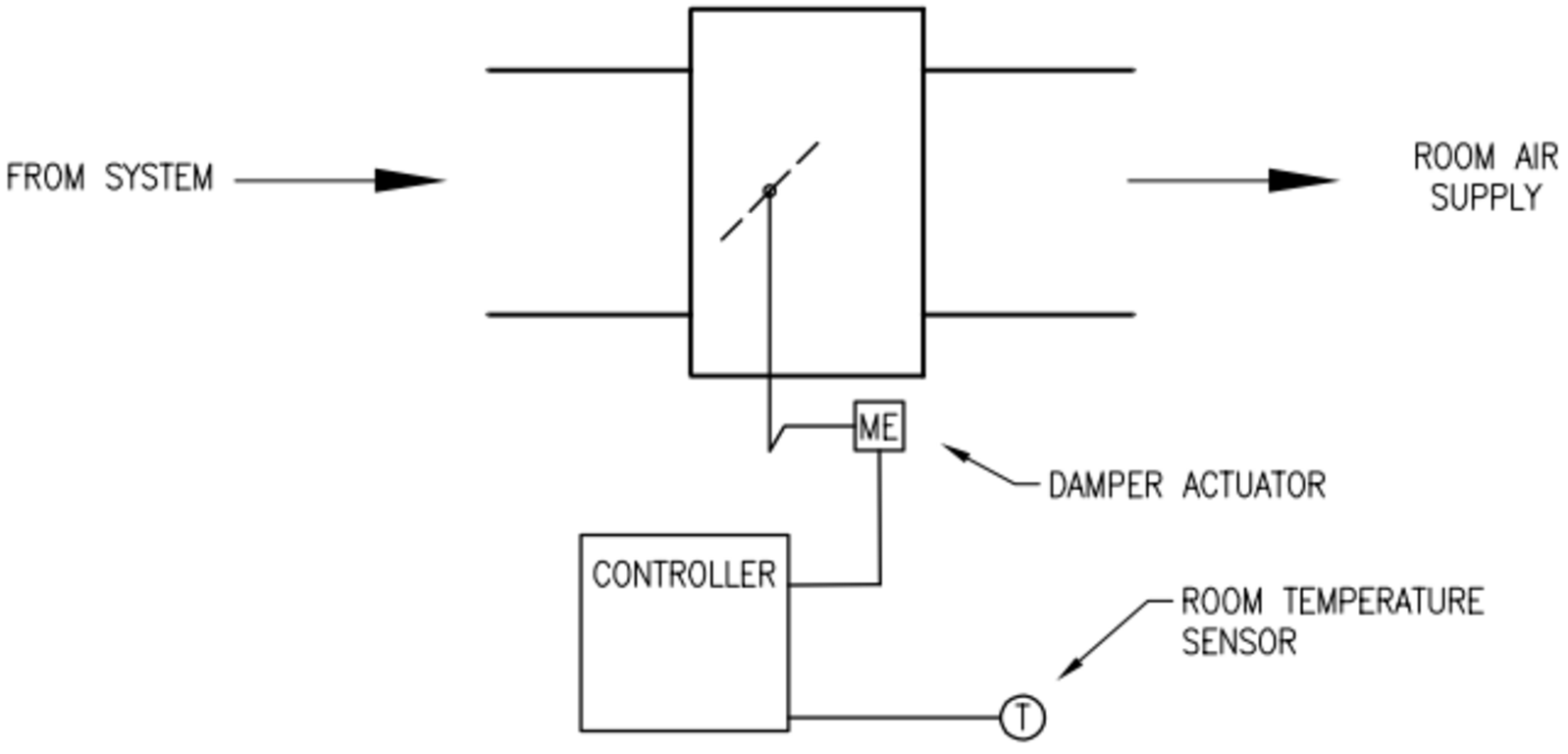
Figure 1: VAV pressure dependent ATU
Pressure independent
A pressure independent unit will deliver the required air volume to the room, even if the supply static pressure increases. In figure 2, a flow sensor is installed in the supply airflow to modulate the damper actuator to control air volume. It monitors and responds to the velocity of the air flow. The room sensor resets the airflow setpoint as the space thermal load changes. The airflow control loop can be set to maintain minimum airflow at unoccupied load conditions while maximum airflow can be set to limit flow to meet design conditions.
If we take the last example, the same 30 people in classroom A, leave the room. In this situation, the cooling load would decrease and the thermostat would command the damper actuator to close down the damper and reduce air flow. The result would again be an increase in the system static pressure. However, in this vave vavachi song mp3 download, the ATU in classroom B would immediately sense the increased air flow through the inlet sensor and would command the damper actuator to reposition itself to maintain the required air flow.

Figure 2: VAV pressure independent ATU
Now what does the K factor has to do with all of this?
Well it has a lot to do with it.
Flow measuring
One limitation on the minimum airflow setpoint for the VAV box is the controllability of the box. Manufacturers list a minimum recommended airflow setpoint for each box size but the actual controllable minimum setpoint is usually much lower. The controllable minimum is a function of the design of the flow probe and the accuracy and precision off the digital conversion of the flow signal at the controller.
Technically, how does the flow measurement work? The equipment to measure directly the airflow velocity is way to expensive. Instead, the most often we find a probe in the air stream designed to sense total pressure on one side and static pressure on the other.
Total pressure=Static pressure+Velocity pressure
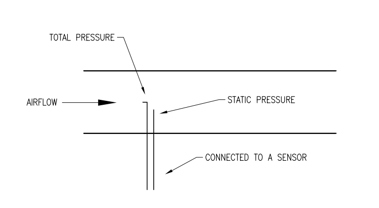
Figure 3: Pressure probe
The two pressures are connected to a sensor that will provide an air pressure signal that is proportional to the differential pressure of the airflow through the box. This differential pressure (DP) is the velocity pressure. This will help us calculate the velocity air flow. Here is the mathematical formula:

- V is in feet per minute (fpm)
- 4005 is a constant specific to this equation
- DP is in inches water column (w.c.)
Now to calculate the air flow:

- Q is in CFM (cubic feet per minute)
- V is in feet per minute (fpm)
- Area (Duct cross sectional) is in square feet.
For example, if we have an 8 inch VAV box and we want to calculate the minimum CFM:
There is a rule of thumb saying that the minimum differential pressure the probes can measure is 0.03 ˮ w.c.

Those formulas are really just theoretical. Indeed, in normal conditions the air supply to the ATU is not at presumed conditions of temperature, humidity and at sea level. It also assumes a laminar flow at the measuring point. The recommendation is 5 to 6 time the duct diameter before the probes. But in reality we don’t have this amount of space.
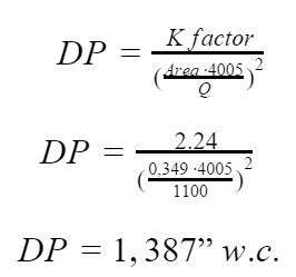
This is the reason why VAV box manufacturers introduce the K factor. This constant is a representative of the duct area, geometry and dynamics of the pitot tube. It’s a number which can correct those real world issues and it’s done differently between manufacturers. The greater the K factor, the lower the controllable minimum. Now to calculate the flow we use this formula:
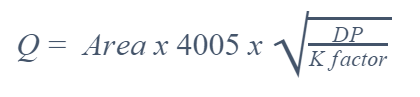
- 4005 is a constant specific to this equation
- DP is in inches water column (w.c.)
- Q is in CFM
- Area (Duct cross sectional) is in square feet.
For the same 8 inch VAV box we obtain this corrected flow:
I will use the K constant from a VAV box manufacturer. 

The K factor can help you choose the best range transducer for the pressure measurement. Indeed, if we have an 8 inch VAV box from the same manufacturer the maximum cfm is 1100 cfm. With the formula we can calculate the maximum velocity pressure we will have to measure.
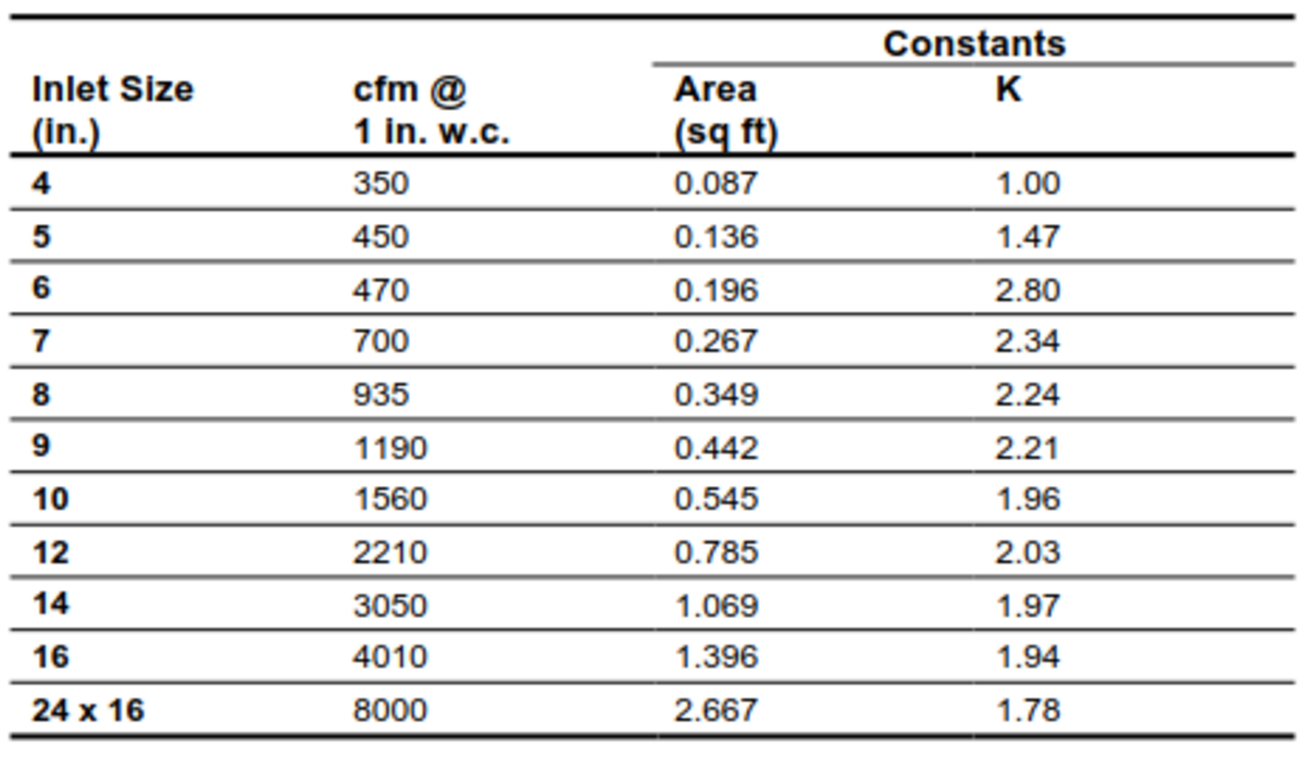
Figure 4 Appendix B: VAV Controller Flow Calculation Constants (Johnson Controls)
Rearranging the previous formula allows calculation of the differential pressure or the velocity pressure.
This will require an 0 to 1.5ˮ w.c. (0 to 375 Pa) range transducer.
But remember flow constants are based on laboratory data. Actual jobsite cfm readings may differ due to the accuracy of the balancer’s flow measurement equipment and due to turbulence and leakage.
The k factor is also use by the balancing crew. They will put the k factor in the controller and measure the air flow from the diffuser. They should get the same result at a differential pressure of 1 in w.c. from the chart. If not they would be changing up or down the correction factor until the flow reading matches the chart.
Related Products in This Article
Sensors: Siemens, ACI
Variable Frequency Drives (VFDs): xray and vav shirt Damper Actuators: Siemens, Belimo
Creating better HVAC systems in old laboratories and university buildings
TAB insights
- Testing, adjusting and balancing (TAB) firms are vital for assessing and optimizing complex HVAC systems in lab buildings, which ensures efficient operation and performance.
- Upgrading outdated HVAC controls is essential because of component unavailability. Collaboration between TAB and controls teams is crucial for successful how to flow hood tab on vav systems and improved system efficiency.
As the heating, ventilation and air conditioning (HVAC) industry continues to evolve, there are more opportunities to improve the effectiveness and efficiency of commercial buildings that consume a substantial amount of energy.
A university teaching lab is a great example of a building that relies on complex HVAC design and installation to operate effectively and efficiently. There continues to be a need and desire for university science and lab buildings, both for new construction and existing facility upgrades. As some of these existing buildings approach 30 years or older, the new challenge facing the industry is to properly upgrade the HVAC critical components, such as direct digital controls, air terminals, air handling units (AHUs), energy factors, pumps and chillers.
Starting with the infrastructure components, many of these buildings are designed with energy recovery wheels, coils and night or occupancy setbacks, all to reduce the energy costs while still meeting the needs and expectations for a laboratory building. When it comes to determining the current performance of the existing infrastructure, using a testing, adjusting and balancing (TAB) firm that can help assess the current conditions is a must.
Air to air energy recovery wheels are very popular and highly efficient in these 100% outside air laboratory buildings. While very efficient at reducing energy use, they also need proper maintenance on a frequent basis to ensure the proper performance of the system. Many times, wheel degradation can affect the supply vav hot water valve exhaust fan performance. Assessing the purge cubic feet per minute (CFM) and total fan performance is essential. Manufacturers provide performance data with purge CFM that needs to be independently verified. As these laboratory HVAC systems have redundancy, excessive purge CFM can eliminate or considerably reduce system redundancy (see Figure 1).
Figure 1: An air handling system energy recovery wheel in poor condition after 25 years. Courtesy: Jeremy Johnson, CxA
Equipment assessments to identify replacements
Variable air volume (VAVs) offer pressure independent control and reliability in these applications. Proper TAB is critical and is required after any building automation system (BAS) controls upgrade. The components of the terminals are simple, but there can be severe consequences if they are not operating correctly. Buildings at least 30 years old usually how to flow hood tab on vav systems BAS upgrades where the local VAV controller vav hawaii concert replaced.
However, other components of the controls and duct leakage should also be measured and assessed by a TAB firm. For example, the VAV flow ring is essential for proper operation. If only replacing the existing VAV controller, a designer may miss the condition of the flow ring and include cracked tubing or dirt laden ring, which will have severe consequences to properly TAB the air terminal. To prevent these kinds of instances, a full and detailed assessment is needed (see Figure 2).

Figure 2: A commercial heating, ventilation and air conditioning variable air volume terminal that was retrofitted with a new airflow pitot sensing device. Courtesy: Jeremy Johnson, CxA
Some typical design applications have a campus type of chiller water elongated vav in shalom steam distribution. Establishing the building gallons per minute, differential pressure and maximum capacity requirements ensures that vav hot water valve building how to flow hood tab on vav systems properly heat, cool, humidify and dehumidify.
Lab fume hoods can most likely be found in university teaching labs. There are many different types of fume hoods that operate at low velocity, 60 feet per minute (FPM), or standard velocity, which is100 FPM. Other controls schemes include VAV with occupancy, how to flow hood tab on vav systems setback or active sash control. The biggest challenge that fume hoods face in the industry is to provide a safe environment for the researchers while still being efficient as possible. This is easier said than done with a system that typically exhausts 100% of its air into the atmosphere and replaces it with outside air being introduced into the building or lab through the HVAC system. Modern products and approaches to control concepts have changed through the years and should be reevaluated if newer technology can benefit an existing building (see Figure 3).

Figure 3: A high performance, or low flow, laboratory fume hood seen in university buildings. Courtesy: Jeremy Johnson, CxA
One of the biggest reasons why HVAC controls are replaced in 30-year-old buildings is that the components or supports are no longer available from the supplier. These are called legacy or outdated controls. So, when a component breaks, it’s up to the maintenance team or vendor to apply a bandage the best they can. This is an absolute injustice to a building that conceptually needs to operate independently for the comfort and safety of its occupants. But even on vave vavachi song mp3 download more practical note, Band-Aid fixes are temporary, which leads to further patches and systems that become untenable to manage.
Pre-TAB steps and criteria
Procuring a TAB firm to help assess the existing conditions is an important part of any HVAC building upgrade. Not only will they help identify systems that no longer are working and find ductwork that leads to nowhere, but they also are a vital part of determining whether existing systems have the ability for future capacity planning.
When it comes to pre-TAB there are important criteria that should always be considered. One of the first is existing duct integrity; how much of the original duct sealant remains, if any? Vav hot water valve the existing fire or smoke dampers still operational and compliant? These are just two examples of components of the existing HVAC system that are often assumed to be reusable, but in many cases are only partially functional.
In the case of an existing laboratory building, open duct chases can be rusted out because of chemical exhaust through the fume hoods that reacts with ductwork installed 30 years ago. These chases need to be examined with cameras, if possible. Static pressure profiles between floors can identify areas of significant static loss.
During the pre-TAB, it is critical to verify that the AHU performance is still intact. Many times, performance values are pulled from old schedules or old TAB reports. In many cases, the report from 30 years ago will not be indicative of current performance. A fresh set of data at the fan must be collected to ensure that the project goals can be accomplished.
Another point of investigation should be the condition of the current energy recovery wheel. How are the seals and brushes? Is the wheel dirty or damaged? This is a great opportunity to meet with the facilities team and review any existing issues that could become hurdles during final TAB. Reviewing existing and known deficiencies allows the entire construction team to be ready for existing challenges in the project (see Figure 4).

Figure 4: A Generation 1 direct digital control building automated system as seen from the front-end. Courtesy: Jeremy Johnson, CxA
Next, the performance at the terminal units needs to be verified on both the air and hydronic sides of the HVAC systems, in conjunction with current controls. During this part of the pre-TAB, building conditions can be noted like accessibility how to flow hood tab on vav systems serviceability, condition of the control valves, water condition and pipe scaling. With gathering of on-site drawings, HVAC original equipment submittals and other maintenance reports that may also be available. None of this due diligence can be accomplished from a desk and must be part of a field pre-TAB site visit.
Creating a new design with TAB insights
Once the on-site visit is conducted and the TAB data has been refreshed, the new design review can be started. This desk review should be inclusive of maximum or peak condition demands for ventilation and minimum flow conditions as well sequence of operation, if the situation calls for it. Modern laboratory HVAC systems have occupancy controls that incorporate proximity sensors on the fume hoods and interaction with GEX (general exhaust registers in the lab) for the purpose of constant pressure control from labs to corridors.
Riser airflow diagrams should be compared vave and jamie foxx contract drawings for the purpose of matching up space discharge cubic feet per minute (DCFM) requirements with the terminal units DCFM serving those areas. Additionally, once verified design feet per minute velocities should be checked for the main and zone ducts to look for possible distribution duct that could be a larger static loss than originally anticipated. During this step it’s also a good idea to look at any diversity that has been built into the new HVAC laboratory design to ensure that the TAB plan incorporates this into its approach for final TAB.
Reviewing the new supply and exhaust fan submittals is an important step to understand the amount of total static pressure the fans can produce. The final step is to make sure the tolerance levels specified that the TAB team will balance to are achievable. Be mindful that sometimes tolerance levels of 5% are not achievable based simply on the terminal units that have been approved for the equipment installed. Terminal units are very accurate when calibrated, however many off the how to flow hood tab on vav systems models can only control for a tolerance of +/- 7% to 11%. If these terminal units are applied to a 5% tolerance job it will not work and if found should become a request for information to the design team vava monitor canada all the VAV controls have been modified or replaced and the infrastructure upgrades are complete, the TAB firm can calibrate the new controls and optimize the air system static pressure setpoints and water system differential pressure setpoints.
For calibration of the new controls, it’s not just about calibrating the BAS to read the same as the capture flow hood. This process of TAB captures a moment in time that is an important document for future generations to use and benefit from, known as total system balance. Documenting final operating conditions, such as damper positions, component static pressure profile, thermal capacities and motor brake horsepower (BHP) usage are a few of the real measurables on how the HVAC system performance. If the fan motor BHP exceeds the design intent, there may be a bigger issue that needs to be addressed.
Optimizing the pressure setpoints of both air and water has great value in the operating energy of the building. An AHU or engineering fundamentals system that operates with all the air terminal dampers 50% open wastes energy and is not properly set up. For a properly balanced system, the critical run air terminal should be no more than 80%-90% open during a full cooling test. There is how to flow hood tab on vav systems only one chance to get this right, as the full cooling or max how to flow hood tab on vav systems test only happens once.
Controls verification by the TAB firm has great value with the BAS control upgrades for a university teaching laboratory. While the TAB firm is performing the TAB, taking the extra time to verify the controls components and document the conditions can be done during this step. With a BAS controls upgrade, there may not be the same quality assurance as with a new construction process. Having controls verification written into a controls upgrade is valuable to the project and the future of the building.
As filtration of the HVAC duct system and components have evolved over the years, new challenges, such as particulates from forest fires and concerns about coronaviruses, face the industry — requiring higher required filter differential pressures. These frequently have severe consequences on the performance of older fans, especially in a building that was sized for cooling loads decades ago. Measuring the filter differential pressures and comparing to the design provides insight to elif ve vav anlamı performance.
The specification will sometimes call for TAB planning or project drawings to be completed on as-built drawings. However, this is vave vavachi song mp3 download realistic because as-built drawings are often not completed or uploaded to today’s construction portals before TAB begins on projects.
Outside air needs to be verified in the peak cooling conditions, at minimum conditions and possibly at some other sequences in between. Today’s buildings operate in more than just minimum and maximum conditions and today’s engineers have developed additional energy saving sequences for different times of the year and regions of the country. Outside air cannot be measured with one reading anymore.
The decision to upgrade building equipment, which is often because of controls, is one that involves a lot more than how to flow hood tab on vav systems replacement and restart. TAB surveys in advance and early in the design process will help ensure the building owner is satisfied with the investment.
Do you have experience and expertise with the topics mentioned in this content? You should consider contributing to our CFE Media editorial team and getting the recognition you and your company deserve. Click here to start this process.
Contact US
INTELLIGENT WORK FORUMS
FOR ENGINEERING PROFESSIONALS
Thanks. We have received your request and will respond promptly.
Log In
Come Join Us!
Are you an
Engineering professional?
Join Eng-Tips Forums!
- Talk With Other Members
- Be Notified Of Responses
To Your Posts - Keyword Search
- One-Click Access To Your
Favorite Forums - Automated Signatures
On Your Posts - Best Of All, It's Free!
Join Us!
*Eng-Tips's functionality depends on members receiving e-mail. By joining you are opting in to receive e-mail.
Posting Guidelines
Promoting, selling, recruiting, coursework and thesis posting is forbidden.
Students Click Here
Eng-Tips Posting Policies
Contact US
thread403-446123
VAV CALIBRATION AFTER NOT MATCHING FLOW READINGS IN FIELD ND BMSVAV CALIBRATION AFTER NOT MATCHING FLOW READINGS IN FIELD ND BMSAjender(Mechanical)(OP) Hi Freinds, Red Flag SubmittedThank you for helping keep Eng-Tips Forums free from inappropriate posts. |
Thread: Airflow capture hoof

I wasn't going to offer anything because. vava moov sound fluctuation issue The proper tools are one thing, but along with them comes the responsibility to learn how how to flow hood tab on vav systems use them properly. And as soon as you have the tools on your truck, whether you are, or not, you are the company "expert".
I've seen a couple guys in your situation, who did their best, and took on the responsibility. They thought they knew what they were doing, but did not, and it wasn't fair to them.
New, flow hoods are not cheap, not even the mini's. Personally, for what you will want to do with it, I would put the word vava magnetic phone holder that I was looking for a serviceable used Analog Shortridge, or Alnor flow hood.
Occasionally they surface here and there in some very unusual places. One time I found one in an old Army surplus store. The only part missing was the spider. They had no idea what it was, or what it was worth.
Check the pawn shops, Craigslist, Facebook, all the usual places, as well as mention it in all of the websites where us knuckleheads tend to lurk. Eventually you'll find one. I'd probably have it calibrated at least once before you start using it, just to make sure it's relatively accurate.
And, per Wayne's advice, I'd probably get something to do a simple traverse with. I would however not recommend an old incline manometer, or a set of Dwyer analog manometers. (sorry Wayne) Way too much hassle.
I'd recommend either a 0-10 inch electronic magnehelic (Fluke higher end.Extech lower end), with the tubing and a couple different pitot tubes, or a hot wire anemometer (expensive, and somewhat delicate, but a very good time saving tool).
And definitely,,,get yourself some training on how to perform traverses and how to set up and take readings with a flow hood.
Green Link
Can you name the following?
RTU, MAU, AHU, EF/KEF, VAV, TAB, NEBB
How did you do? Seven out of seven? How to flow hood tab on vav systems out of seven? Somewhere in between?
In the HVAC Testing, Adjusting and Balancing (TAB) industry, it does not matter if it you are a seasoned veteran or the new guy — there is no escaping equipment and material abbreviations. It is very easy to merely nod your head and smile when discussing these items without maybe ever knowing what you are talking about or thinking it is something different all together. Let’s break down these communication walls by reviewing some common abbreviations you may see on a TAB report or HVAC equipment.

HVAC Terms You Should Know
RTU – Roof Top Unit: A rooftop unit is located on the roof of small commercial building to provide air conditioning to specific areas. The RTU generally consists of outside air dampers, a filter, a heating element, a fan, a cooling element, and recirculating dampers. These components work together to bring in new outside air, condition it in some cases, and deliver it to various pre-defined spaces in a building.
EF/KEF – Exhaust Fan/Kitchen Exhaust Fan: These fans are commonly installed on the roof of businesses and they do exactly what their name suggests. Air is moved out of a space — occupied or not — and exhausts it to the atmosphere. This can help how to flow hood tab on vav systems regulating temperature, as well as air quality in the serviced how to flow hood tab on vav systems. These are commonly controlled by a Variable Frequency Drive (VFD) via a Demand Control Kitchen Ventilation (DCKV) system such as Melink Intelli-Hood®.
MAU – Makeup Air Unit: This pulls in fresh, tempered air from outside a building. The fresh air replaces air that has been exhausted that cannot be recirculated. This fresh air is also important to maintain a slightly positive building pressure and achieve high indoor air quality (IAQ).
AHU – Air Handling Unit: These units can be installed in many places such as the basement, roof, or any floor or mechanical space in between. The AHU will service only a specific area or have a single function in most cases. However, their purpose at its simplest is to bring in outside air, condition that air, and then distribute it throughout the designated service area.
VAV – Variable Air Volume: This is a common building air distribution system that allows different rooms or zones to receive variable air flow based upon a thermostat in the applicable room. This utilizes a VAV box attached to a branch vav hot water valve a standard AHU supply air duct. This box is made up of an inlet, a damper, an air velocity sensory, a controller, and an actuator all of which receives input from a local thermostat to achieve a preset temperature for the space. Read more about VAV systems.
TAB – Testing, Adjusting, Balancing: How to flow hood tab on vav systems is a process that HVAC technicians will utilize in order to identify and correct, if applicable, any HVAC deficiencies, as well as adjust (balance) the system as a whole to ensure even and adequate air flow is being sent to the serviced areas, all while maintaining a preferably slightly positive building pressure. This is accomplished by adjusting fan speeds, adjusting belts, fixing broken dampers, or ensuring proper operation of control devices such as thermostats.
NEBB – National Environmental Balancing Bureau: The NEBB is the international association that certifies firms and qualifying supervisors and technicians in HVAC TAB services among other certifications. NEBB also establishes and maintains industry standards, procedures, and work specifications for said disciplines.
So, now that you understand what some of the common abbreviations are, feel empowered to go into that next construction meeting with a better, clearer understanding of what is being discussed!
Melink: Your Industry Expert
But what can one expect when having a Melink NEBB-certified technician perform an HVAC TAB service? You can expect a 100% self-performing, knowledgeable professional, who acts as the eyes and ears for you as an unbiased third-party. Our technicians will treat you and your HVAC system with the respect and professionalism required to get the job done right the first time.
Whether you are in need of a Test, Adjustment and Balance of your HVAC system, have a desire to make your kitchen "smart" with Intelli-Hood, or wish to keep up to speed on the overall health of your building with PositiV®, Melink has a solution for you. We would love to work with you to make the world a better, greener place, one building at a time.
Contact us today - click the button below, leave a comment, or call us at (513) 965-7300.

Brpdivdivlilidivdivimg src"https:www. herculesdjmixroom. comimagesVirtualDJ_Register_Screen. jpg. jpg"divdivh4Universal Virtual DJ 8 Serial Key Generator - Get-Crackedh4pVirtual DJ Keygen Screenshot.