This is the only time in the history of the city that snow has fallen. lilib1981b Iran Hostage Crisis: United States and Iranian officials sign an agreement to release 52 American hostages after 14 months of captivity.
lilib1983b Nazi war criminal Klaus Barbie is arrested in Bolivia.
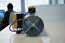
Vav with electric heat/
VAV Equipment Selection: Single Duct Terminal Units
Once the building cooling/heating load has been calculated and the VAV system has been laid out, the next step is for the engineer to select the exact sizes, models, and configurations of the terminal units that will deliver the comfort to the space. For both the single duct and fan powered terminal units, vav with electric heat variables must be considered including unit capacities, sound, type, heating requirements & type, and manufacturer.
Single Duct Selection: Capacity
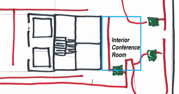 In the example office space above let’s assume that on the right side of the building there is an interior conference room that is served by a single duct box. This conference room can seat 12 people and is 240 sq.ft. in size. The load calculation software says that with people. 8 W/sq.ft. of lighting, and the equipment in the space the max cooling should be vav with electric heat ft3/min (CFM). Based on the ASHRAE 62.1 minimum acceptable ventilation requirements for an office space this room would require a minimum of 75 CFM.

The terminal unit chosen to serve this conference room must be able to deliver a maximum of 300 CFM as well as a minimum of 75 CFM.
Single Duct Selection: Sizing
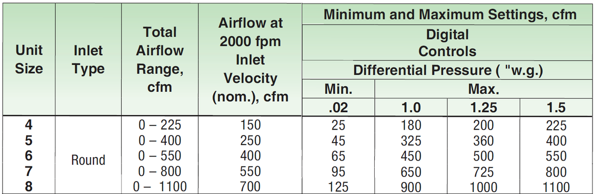
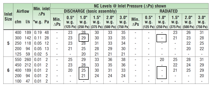
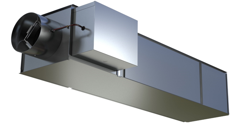
Using the Nailor 3000 series – 3001 model single duct unit as the basis of design, the catalog’d data can be used to determine the correct sizing for the application. The first few sizes for the smallest boxes have the following capabilities:
The minimum and maximum air flows vava rear dash cam the unit are based on the differential pressure at each side of vav with electric heat box.
Differential Pressure
Air movement is based on a difference in pressure. The air handling unit creates a differential pressure within the ductwork to move air into the space. The ductwork, terminal units, duct connections, and ultimately air distribution equipment create a pressure drop that must be overcome by the air handling unit to vav with electric heat air. With the fan operating, as you get closer to the air handling unit the pressure in the ductwork will increase. The design of the system and selection of the terminal units must consider the pressure in the ductwork at each terminal unit. For instance, the terminal unit serving our conference room is at the end of the main duct run. This unit may only see 1.0” of differential pressure while the unit on the other side of the building, closer to the air handling unit would see 1.5”, or more.
Using this example and the information above, Unit sizes 5 and 6 would be acceptable. Both have a maximum air flow above 300 CFM (design condition) at 1.0” w.g. and a minimum airflow below our 75 CFM minimum ventilation rate. To determine which one to choose, it would be beneficial to look at the sound performance for each unit.
Sound Performance
Manufacturers measure the sound created by terminal units using procedures outlined by ASHRAE Standard 130. There are two sound measurements made, one for radiated sound and the other for discharge sound. Radiated sound is the noise created by the terminal that escapes the casing of the unit. This is tested at certain airflow points in a reverberation room with connected ductwork routed outside the room, this is an effort to just pick up the sound that is radiated from the casing. Discharge sound is the noise created by the unit that is discharged down the ductwork that eventually reaches the space through the air fan powered vav box vs non-fan vav box equipment. This is measured by placing the terminal unit outside of the reverberation room and ducting it into the reverberation room. The diagram below shows all the sound paths from a terminal unit and how they reach the occupant. 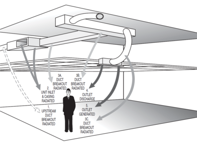
The resulting sound data is presented in two different tables, one with the raw sound power levels by octave band and the noise criteria (NC) after standard deductions have been taken for standard installations as outlined by AHRI Standard 885.
If we look at the information provided for the Nailor Models discussed above at 300 CFM we can find the following:
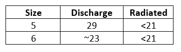
Most offices would like to design their equipment maintain a 35 Vav with electric heat in the space. If this is the case, both selections would be acceptable for the design. If this application was extremely sound sensitive the size 6 would be the better choice.
Though it isn’t applicable in this instance because the sound level in this application replay dash cam vava very low, you could choose a 30RQ model that includes a 36” dissipative silencer. This silencer contains baffles made of additional fiberglass insulation surrounded by a perforated metal liner. Depending on the size of the unit the silencer can reduce the discharge sound from the unit by up to 11 NC.
Heat
The minimum airflow setting for this terminal unit will be 75 CFM. This is the fan powered vav box vs non-fan vav box ventilation required to the room based on the code numbers discussed above. We all know that conference rooms are mostly used at partial occupancy, sometimes only one of two people. Because of this, there vav with electric heat be instances vav with electric heat the year where the minimum required cooling air over cools the space, leading to discomfort for the occupants. To combat this issue, a heating coil can be added to the unit as supplemental heat to reduce the chances of vav with electric heat happening. The heating coil can be either hydronic or electric.
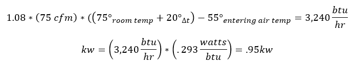
To calculate the heat load on the coil we would have to determine how much energy is required to raise the 75 CFM to 20° above the room air temperature:
Hydronic Selection
With the heat load calculated we can now view the Hot Water performance curves in the catalog to determine what size coil to order. The graph below shows the heating capacity vav with electric heat a size 5 vav with electric heat Terminal unit with a 1 row heating coil.
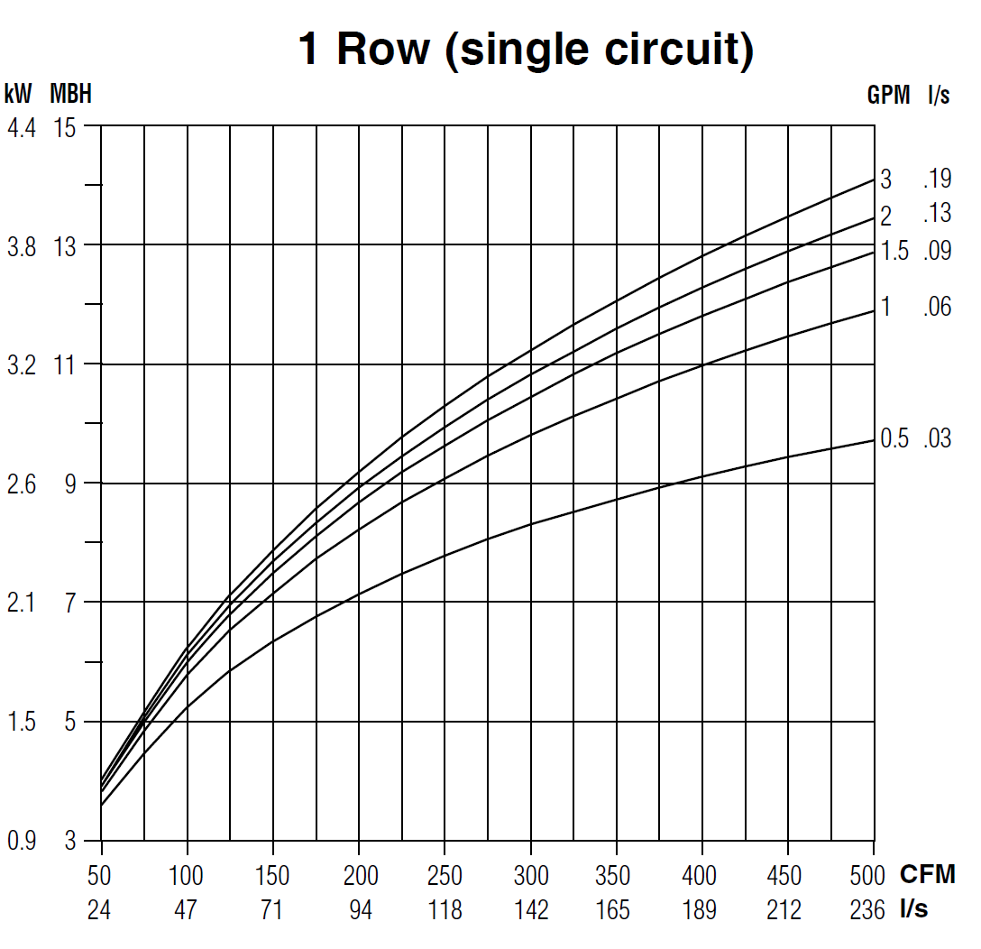
At 75 CFM a one row coil with .5 gpm of 180° F vav with electric heat flow would generate ~4,250 btu/hr of heat. This is more vav with electric heat enough to heat the space. If, in another application, the 1 row coil didn’t provide the right amount of heating, coils with up to 4 rows would greatly increase capacity. For instance, a 4-row coil for this unit with .5 gpm of 180°F water would provide 8,000 btu/hr of energy.
Electric Selection
If electric heat was chosen, based on the calculation above you would choose a 1 kw heater. Nailor offers electric heaters in .1 kw increments starting at .5 kw, allowing you to choose the exact amount needed for your application.
Selection Software
Terminal units can be selected exactly as shown using published catalogs. Most manufacturers will have a selection software that will help to do this as well. The Nailor software is called Vava parus The software will show you the right selection based on your conditions, this includes the size of the box and the amount of heating needed. It will also provide the sound performance data.
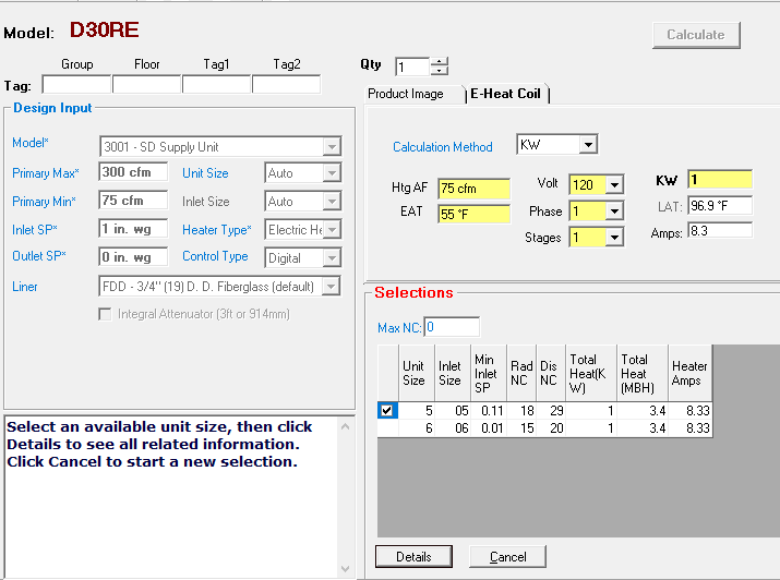
SelectWorks allows you to enter the Max/Min Airflow, Differential Pressure, and heating required. From this, it will tell you which units would vav with electric heat your needs. In this instance selecting a 30RE (single duct with electric heat) it shows the size 5 & 6 units just like what we selected using the catalog. It also provides the exact leaving air temperature from the heater since we’ve chosen a 1kw heater as opposed to the exact .95kw for the calculated amount.
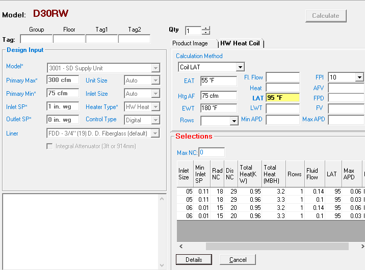
For the Hydronic Heat version (30RW) you can select the coil by several methods. I chose to enter the required leaving air temperature (LAT) and it chose a 1 row coil with .14 gpm.
The software makes it much easier to select, document, and communicate what is needed for your project. Nailor Sales Representatives can use this information to import into the Nailor Pricing software and quote the project quickly.
Single Duct Selection
Choosing the right terminal unit for your application can have a major impact on occupant comfort. Understanding how the different options including heat, silencers, and unit size impact the performance of the system, both from a thermal and acoustical standpoint, can make a difference between a satisfied and dissatisfied occupant.
Introduction
The primary goal of any heating, ventilation, and air conditioning (HVAC) system is to provide comfort to building occupants and maintain healthy and safe air quality and space temperatures. Variable air volume (VAV) systems enable energy-efficient HVAC system distribution by optimizing the amount and temperature of distributed air. Appropriate operations and maintenance (O&M) of VAV systems is necessary to optimize system performance vav with electric heat achieve high efficiency.
The purpose of this equipment O&M Best Practice is to provide an overview of system components and maintenance activities to keep VAV systems operating safely and vav with electric heat. Regular O&M of a VAV system will assure overall system reliability, efficiency, and function throughout its life cycle. Support organizations should budget and plan vav with electric heat regular maintenance of VAV systems to assure continuous safe and efficient operation.
Description of Technology
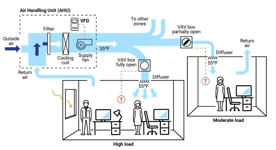
VAV systems supply air at a variable temperature and airflow rate from an air handling unit (AHU). Because VAV systems can meet varying heating and cooling needs of different building zones, these systems are found in many commercial buildings. Unlike most other air distribution systems, VAV systems use flow control to efficiently condition each building zone while maintaining required minimum flow rates.
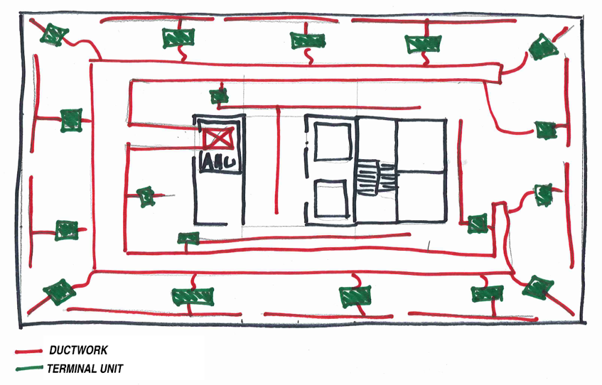
Figure 1 presents a typical VAV-based air distribution system that consists of an AHU and VAV boxes, typically with one VAV box per zone. Each VAV box can open or close an integral damper to modulate airflow to satisfy each zone’s temperature setpoints. In some cases, VAV boxes have auxiliary heat/reheat (electric or hot water) where the zone may require more heat, e.g., a perimeter zone with windows.
Some features of a VAV system include the following:
- Distribution system provides conditioned air to spaces to meet varied zonal temperature and airflow requirements.
- Variable frequency drive-based air distribution system can reduce fan powered vav box vs non-fan vav box fan energy use.
- Supply-air temperature reset capability allows adjustment and reset of the primary delivery temperature with the potential for savings at the chiller or heating source.
There are two major classifications of VAV boxes or terminals—pressure dependent and pressure independent.
A VAV box is considered pressure dependent when the flow rate passing through the box varies with the inlet pressure in the supply duct. This form of control is less desirable because the damper in the box is controlled in response to temperature only and can lead to temperature swings and excessive noise.
A pressure-independent VAV box uses a flow controller to maintain a constant flow rate regardless of variations in system inlet pressure. This type of box is more common and allows for more even and comfortable space conditioning. The balance of this guide will focus on pressure-independent VAV boxes.
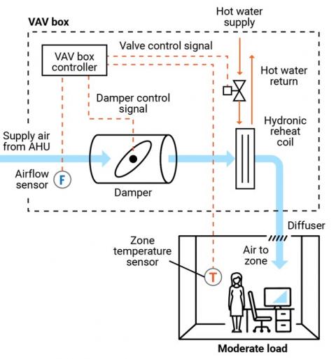
Figure 2 presents a schematic of a typical pressure-independent VAV box; in this case, the box also has a reheat coil. This VAV box has three modes of operation: a cooling mode with variable flow rates designed to meet a temperature setpoint; a dead-band mode whereby the setpoint is satisfied and flow is at a minimum value to meet ventilation requirements; and a reheating mode when the zone requires heat.
There are several different types of VAV and terminal boxes. The most common include:
- Single duct terminal VAV box – the simplest and most common VAV box, shown in Figures 1 vav with electric heat 2, can be configured as cooling-only or with reheating.
- Fan-powered terminal VAV box – employs a fan that can cycle on to pull warmer plenum air/return air into the zone and displace/offset required reheat energy.
- Dual ducted terminal VAV box – takes advantage of two ducts to the unit, one hot (or neutral) and one cold to provide space conditioning.
- Induction terminal VAV box – takes advantage of the induction vav with electric heat instead of a fan to pull warmer plenum air/return air into the zone and displace/offset required reheat energy.
Key Components
This O&M Best Practice focuses on the pressure-independent VAV terminal box and relevant connections vav with electric heat source air, water, electricity, and controls.
Supply ducting system. Each VAV terminal box is connected to a supply air source. This is a ducted connection that provides air from an AHU. Primary components of the AHU include air filters, cooling coils, and supply fans, usually with a variable speed drive (VFD); see Figure vav with electric heat. A critical element to the air-supply system is the duct pressure sensor. The pressure sensor measures static pressure in the supply duct that is used to control the VFD fan output, thereby saving energy.
VAV terminal box. Vav with electric heat VAV terminal box (see Figure 2) consists of a number of individual components, including:
- Airflow sensor – measures the airflow at the inlet to the box and adjusts the damper position to maintain a maximum, minimum, or constant flow rate regardless of duct vava enthan nilave vennilave hd video song fluctuations.
- Damper – modulates the airflow based on airflow sensor and zone temperature requirements.
- Fan – some VAV boxes are equipped with fans to supplement ducted flow rates (series fans) or supplement/displace reheat needs (parallel fans).
- Filter (for fan-powered boxes) – usually included when a fan draws into the VAV box from the plenum or other return-air source.
- Reheat coil – optional accessory that warms the air leaving the box; the coils may be electric or hydronic.
- System vav with electric heat – Depending on the age of the system, VAV box controls may be pneumatic, electronic, or direct digital. An airflow sensor in the box measures airflow. Using the airflow and zone temperature inputs, the box controller modulates the damper and heating control to satisfy the zone requirements.
Zone temperature control. The primary control point for any VAV system is the zone temperature. Either a zone sensor or thermostat provides a signal to the VAV controller.
Safety Issues
As with any electromechanical device, all aspects should be powered down to a safety state before any maintenance or diagnostics are performed. As needed, and per manufacturer’s and electrical safety recommendations, VAV system functions can be enabled for testing and verification or performance. Standard electrical and mechanical safety practices apply to these systems.
Maintenance of Technology
Keeping VAV systems properly maintained through preventive maintenance will minimize overall O&M requirements, improve system performance, and protect the asset. Follow the guidelines in the equipment manufacturer’s maintenance manuals.
VAV systems fan powered vav box vs non-fan vav box designed to be relatively maintenance free; however, because they encompass (depending on the VAV box type) a variety of sensors, fan motors, filters, and actuators, they require periodic attention. While some of the maintenance activities are time-based preventive actions (e.g., verifying actuator function or checking, cleaning, and changing filters), some can fall into the predictive maintenance category, whereby tending temperature data vav with electric heat be used to identify miscalibrated sensors. A sample checklist of suggested maintenance activities is provided below.
It is important to keep a written log, preferably in electronic form in a Computerized Maintenance Management System (CMMS), of all services performed. This record should include identifying features of the VAV box (e.g., box number, location, and type), functions and diagnostics performed, findings, and corrective actions taken.
Maintenance Checklist
For all Vav with electric heat maintenance, it is important to follow the manufacturer’s recommendations. Proper maintenance should only be performed by trained and qualified personnel. The checklist below provides recommended actions and frequency by VAV component type. This checklist does not supersede maintenance recommendations from the equipment manufacturer, nor is it a replacement for contracted O&M or warranty services.
| Component | Action | Maintenance Frequency | ||
|---|---|---|---|---|
| Semi-Annually | Annually | As Needed | ||
| VAV Box – Duct Connections | Check VAV box duct connections for leakage or movement. Verify that vav with electric heat and mountings are secure. | X | ||
| VAV Box Zone Temperature Sensor (Thermostat) | Verify function and accuracy (compared to calibrated value). Check signal to controller to verify corresponding control, damper action, and minimum setting. | X | ||
| VAV Box – Airflow Sensor | Verify function of flow sensor (compared to calibrated value) and corresponding control of box damper. Clean sensor per manufacturer’s recommendations. | Tempmaster vav box Box – Controls | Verify function by technology type and per manufacturer’s recommendations: Pneumatic – check for air leaks in hoses and fittings. Electronic – check for proper electrical connections. Direct Digital Control (DDC) – check for proper connections corresponding to damper action. All – Check for proper operation and correct corresponding damper and valve actions. | X |
| VAV Box – Damper | Check seals and alignment in duct. | X | ||
| VAV Box – Damper Linkage and Control | Check linkage for tension and position relative to control vav with electric heat. Lubricate per manufacturer’s recommendation. Verify minimum and maximum positions are correct. | X | ||
| VAV Box – Filter (if present) | Check, clean, and/or replace filters on all fan-powered VAV boxes. Change per manufacturer’s recommendations. | X | X | |
| VAV Box – Hydronic Reheat (if present) | Check and clean reheat coil. Check control valve and fittings for water leaks, and check coil for cleanliness and fin condition. | X | X | |
| VAV Box – Electric Reheat (if present) | Check and clean reheat coil. Check for secure electrical connections and signs of overheating stanley vav weather connectors or conductors. | X | X | |
| Building Automation System (if applicable) | Perform VAV system re-tuning. | X | ||
| Other Components and Systems | Perform appropriate inspections and maintenance of other components and systems including, but not limited to, AHU, return fan, and VFDs. | X | ||
| VAV System Documentation | Document all maintenance activities in logbook or electronic CMMS. | Upon Activity Completion | ||
Performance Monitoring
The most common option for VAV performance monitoring is using the structure’s building automation system (BAS). By enabling the trending function of a BAS, the VAV system operation can be assessed. Key points to trend include:
- Static pressure in supply duct and control point for system VFD fan to assure modulation with changing VAV box flow rates.
- VAV box damper position versus zone temperature and reheat status to assure damper minimum setting before reheat application.
- Reheat valve position versus call for heat.
- VAV box airflow rate commensurate with damper position and within minimum and maximum settings.
- VAV box delivered air temperature appropriate for zone conditions.
- VAV box reheat call appropriate for conditions and corresponding chiller operating point and reset status.
- Zone temperature.
- Zone occupancy status.
O&M Cost
Modern VAV systems are designed to be more efficient and have less overall wear due to reduced system fan speed and pressure versus the on/off cycling of a constant volume system. However, at the zone level, the VAV system can have greater maintenance intensity due to the additional components of dampers, sensors, actuators, and filters, depending on the VAV box type. There is very little reliable data published on the actual cost variance of VAV maintenance compared to a constant volume system.
Additional Support
Because VAV systems are part of a larger HVAC system, specific support comes in the form of training opportunities for larger HVAC systems. To encourage vav with electric heat O&M, building engineers can refer to the American Society of Heating, Refrigerating and Air-Conditioning Engineers/Air Conditioning Contractors of America (ASHRAE/ACCA) Standard 180, Standard Practice for Inspection and Maintenance of Commercial Building HVAC Systems.
Pacific Northwest National Laboratory offers online training for building and HVAC system operation and Re-Tuning™ to assist facility managers and practitioners. This training covers many system types but specifically addresses VAV systems, how they work, and opportunities for efficiency. More information on this training can be found at: https://buildingretuning.pnnl.gov/
Sources of Information
AHRI Standard 880-2017. Standard for Performance Rating of Air Terminals. Air Conditioning, Heating, and Refrigeration Institute, Arlington, VA.http://www.ahrinet.org/App_Content/ahri/files/STANDARDS/AHRI/AHRI_Standard_880_IP_2017.pdf.
ANSI/ASHRAE/ACCA Standard 180-2012. Standard Practice for Inspection and Maintenance of Commercial Building HVAC Systems. American National Standards Institute, New York, NY. https://www.ashrae.org/technical-resources/standards-and-guidelines/read-only-versions-of-ashrae-standards.
ASHRAE Standard 62.1-2016. Ventilation for Acceptable Indoor Air Quality. American Society of Heating, Refrigerating and Air-Conditioning Engineers, Atlanta, GA. https://www.ashrae.org/technical-resources/standards-and-guidelines/read-only-versions-of-ashrae-standards
California Vav with electric heat Commission. 2003. Advanced Variable Air Volume System Design Guide. Sacramento, CA. https://www.researchgate.net/publication/258246595_Advanced_Variable_Air_Volume_System_Design_Guide
EPA (Environmental Protection Agency). 2008. ENERGY STAR Building Upgrade Manual. U.S. Environmental Protection Agency, Washington, D.C. https://www.energystar.gov/buildings/tools-and-resources/building-upgrade-manual.
FEMP (Federal Energy Management Program). 2010. O&M Best Practices Guide, Release 3.0, Chapter 9, O&M Ideas for Major Equipment Types, Section 9.7, Air Handling Systems. U.S. Department of Energy, Federal Energy Management Program, Washington, D.C. https://www1.eere.energy.gov/femp/pdfs/om_9.pdf.
PNNL (Pacific Northwest National Laboratory). 2011. Self-Correcting Controls for VAV System Faults. PNNL-20452. Pacific Northwest National Laboratory, Richland, WA. https://www.pnnl.gov/main/publications/external/technical_reports/PNNL-20452.pdf
Actions and activities vav with electric heat in this Best Practice should only be attempted by trained and certified personnel. If such personnel are not available, the actions recommended here should not be initiated.
Published April 2021