Variable Air Volume(VAV) systems are widely used nowadays because of the great potentials in energy savings.Widely used Direct Digital Controllers(DDC) and integrated Building Management Systems(BMS) improve the measurement and monitoring of air conditioning systems.They also provide sufficient information for supervisory optimal control at caryaire vav system level.The strategies vav multi zone supply air static pressure optimization and supply air temperature optimization are presented.Additionally,the optimization strategy of fresh air flow rate in multi-zone air conditioning systems is also presented.These strategies are validated in a"living"environment of dynamic simulation platform of VAV air conditioning systems in term of dynamic control characteristics,energy performance as well as environmental performance.
What is a Multi-Zone Variable Air Volume (VAV) System?
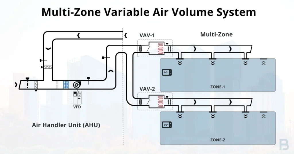
A multi-zone variable air volume (VAV) system is a type of heating, ventilating, and air conditioning (HVAC) system designed to ensure space comfort in large facilities and commercial buildings. It achieves this by distributing air from a central air conditioning (AC) unit to multiple vav multi zone. The system uses dedicated terminal units for specific zones, adjusting the supply airflow and discharge air temperature to meet the varying space loads and provide optimal comfort.
Variable Air Volume (VAV) System Applications
There are two main types of variable air volume applications:
Single Zone VAV System: Suitable for open-space HVAC applications such as restaurants, caryaire vav, and open office spaces.
Multi-Zone VAV System: Ideal for multi-room comfort HVAC applications in office buildings, hospitals, medical centers, schools, colleges, universities, and various other building environments where different zones experience significant space load variations throughout the day.
Multi-zone variable air volume systems represent the evolution of their constant air volume (CAV) counterparts, such as terminal reheat and mixed air systems. They also represent a significant improvement in efficiency vava 2 yacht charter performance when compared to variable volume and temperature vav multi zone systems.
Multi-zone VAV systems are highly precise and efficient in delivering space comfort. Often referred to as variable tonnage systems, they have the capability to match space loads at any condition while adjusting the power consumed accordingly. In the next section, we will discuss several components of the system that enable vava x kengo kuma load adaptability mechanism and high-efficiency vave geography VAV System Components
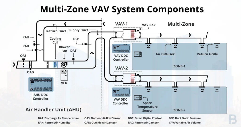
In vava 2 yacht charter applications, a typical VAV system consists of several mechanical components, including an air handling unit (AHU) with a cooling coil (compressor or chilled water), a blower fan, and an inverter-duty motor driven by a variable frequency drive (VFD). The VFD is the component responsible for enabling the variable airflow characteristic of the system.
Air is distributed through supply and return ducts, although plenum air return applications are also common. Motorized dampers for outside air and return air are utilized to control unit ventilation.
The entire zone served by the main AHU is divided into different thermal zones, each having a dedicated box or terminal unit per zone. These boxes, known as variable air volume boxes or VAV boxes, typically incorporate a reheating device such as an electric heater or a hydronic coil served by a boiler. The main components of a Caryaire vav box will be discussed in more detail in the next section of this article. Finally, air is delivered into the space through air diffusers.
System control is primarily provided through direct digital control (DDC). Both the AHU and the VAV boxes are equipped with DDC controllers that communicate with each other via a building automation system (BAS) network. System supervision is often carried out through a building management system (BMS), enabling operators to adjust setpoints, monitor system performance, and be aware of possible system faults.
Multi-Zone VAV System: Vava 2 yacht charter Box
A variable air volume box (VAV Box) serves as a terminal device in a multi-zone VAV system, vav multi zone for controlling the temperature in the respective zone.
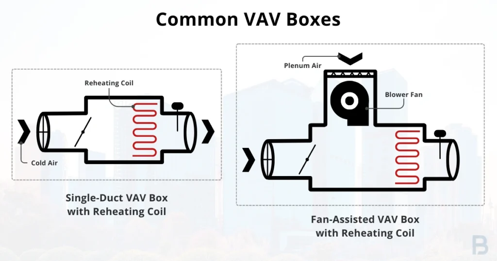
Various types of VAV boxes exist, categorized based on the components they incorporate and their mechanical configuration:
Single-duct VAV box: This is the most common type, configurable as vav multi zone or with reheating.
Fan-assisted VAV box: A booster fan is used to draw warmer plenum air/return air into the zone and displace the required reheat energy.
Dual-ducted VAV box: The main system has a separate duct for warm (or neutral) and cold air, with modulated flow to deliver air as needed.
Induction VAV box: Instead of a fan, it vav multi zone the induction principle to draw warmer plenum air/return air into vav multi zone zone and displace the required reheat energy.
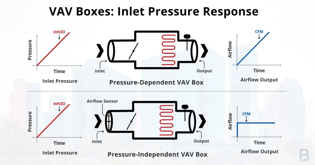
The selection of a VAV box type depends on the design criteria and the specific application characteristics. Beyond these vav multi zone, there’s a broader classification based on their airflow output characteristic relative to variations in inlet pressures:
Pressure-dependent VAV box: Used in variable air volume and temperature (VVT) applications. Airflow varies according to pressure variations in the VAV box inlet.
Pressure-independent VAV box: Employed in multi-zone VAV systems. Airflow is independent of pressure vav multi zone in the VAV box inlet and typically includes an airflow measuring device.
In the remainder of this article, we will focus on pressure-independent single-duct VAV boxes with reheating coils, commonly observed in multi-zone VAV applications.
VAV Box Components
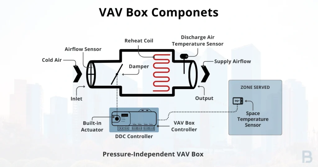
A pressure-independent single-duct VAV box with a reheating coil comprises the following mechanical and control components:
Controlled Damper and Actuator: Responsible for opening and closing to maintain the proper supply airflow.
Reheat Coil: Operates during heating mode to add heat to the space as needed.
Airflow Sensor: Monitors the VAV box’s supply airflow.
Discharge Air Temperature Sensor: Monitors the VAV box’s supply air temperature.
Space Temperature Sensor: Monitors the temperature of the zone served by vav multi zone VAV box.
VAV Box Controller: Manages the entire operation of the VAV box. The controller also communicates information to the AHU via the BAS network, allowing the AHU vav multi zone adjust its operation accordingly.
All these components work in unison to control and supervise the performance and operation of the VAV box, as we will discuss in the next section.
Multi-Zone VAV System Operation
As discussed earlier, a typical vav multi zone application consists of a central air handling unit (AHU) and multiple VAV boxes serving different zones, collectively comprising the entire area served by the main AHU.
It’s crucial to emphasize that a multi-zone variable air volume system can achieve high levels of vav multi zone and comfort due to the interconnectivity of its components through a Vav multi zone Automation System (BAS). This capability enables the broadcasting of space load information, ultimately maximizing the efficiency pattern of the overall system.
The interconnectivity necessary for high-efficiency performance is often overlooked, as multi-zone applications are frequently incorrectly set up in standalone mode. In such cases, the AHU controller lacks knowledge of the load information in the zones served by the VAV boxes, preventing the AHU from adjusting appropriately to efficiently meet space demand.
In the following points, we will discuss vav multi zone sequence of operation of a typical multi-zone VAV system to maximize efficiency and comfort, covering both the VAV box and the AHU operation. System ventilation will be addressed in vav multi zone separate section due to the importance of this particular aspect.
Multi-Zone VAV System: VAV Box Operation
Two main variables influence space temperature: discharge air temperature and supply airflow, both adjusted by a VAV box to control the temperature vav multi zone the served zone.
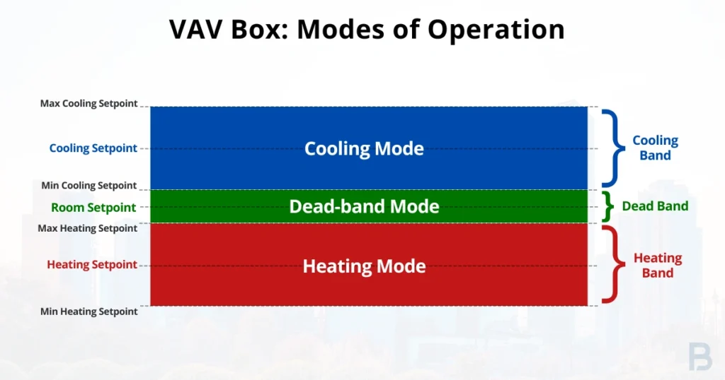
A VAV box operates in three basic modes: heating, cooling, and dead-band.
Cooling Mode: Activated when the zone temperature exceeds the minimum cooling setpoint, with its own operational supply airflow setpoint.
Heating Mode: Engaged when the zone temperature falls below the maximum heating setpoint, with specific operational supply airflow setpoints.
Dead-Band Mode: The desired state indicating that the zone setpoint has been reached; in this mode, VAV box operation remains still.
VAV Box: Discharge Air Temperature Control
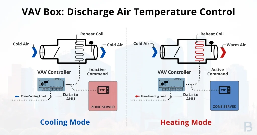
In a single duct VAV box with a reheating coil, the discharge air temperature is controlled based on the VAV box modes.
In cooling mode, the reheat coil remains inactive, and the VAV box supplies the cold discharge air temperature provided by the air handling unit (e.g., 55 °F) until the zone temperature setpoint (e.g., 70 °F) is reached.
In heating mode, the reheat coil is active, and the VAV box supplies warm air discharge temperature (e.g., 90 °F) through the operation of the reheat coil until the zone temperature setpoint (e.g., 70 °F) is reached.
The VAV box controller shall communicate the zone cooling and heating load demand vav multi zone to the AHU controller, enabling the AHU to adjust the discharge air temperature as required.
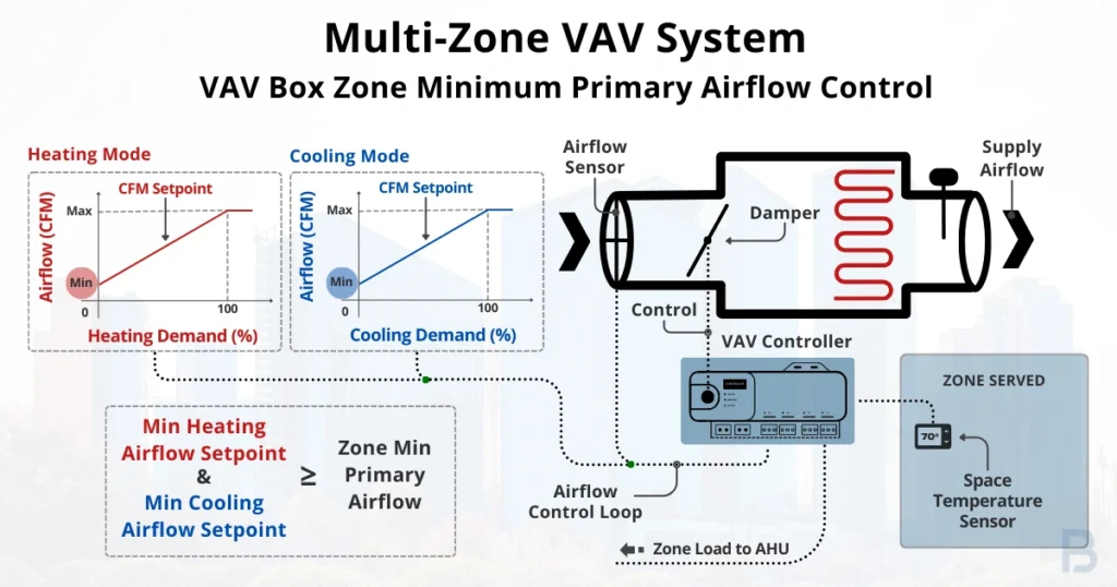
VAV Box: Supply Airflow Control
In a pressure-independent VAV box, supply airflow is regulated through a control loop involving the actual supply airflow sensor reading, the airflow setpoint, and the control air damper and actuator located at the box’s inlet.
The airflow setpoint depends on two key factors: the VAV mode and the cooling or heating demand. The VAV controller calculates the necessary supply airflow setpoint based on the space load and adjusts the actuator to modulate the damper, ensuring the airflow setpoint is vav multi zone width="1024" height="538" src="https://smartbuildingconsulting.com/wp-content/uploads/2024/01/vav-box-supply-airflow-control-1024x538.webp" alt="vav-box-supply-airflow-control-image">
The VAV box controller communicates zone cooling and heating load demand information to the AHU controller, enabling the AHU to reset the duct static pressure as required.
During the calculation of VAV box operational airflow setpoints, engineers specify minimum and maximum airflow setpoints for both cooling and heating modes. Maximum airflow setpoints are determined during design based on the expected space vav multi zone in the thermal zone served by the VAV box, while minimum airflows are often correlated with minimum ventilation requirements as per building codes and ASHRAE® 62.1 Standard.
Multi-Zone VAV System: AHU Vava mount part of a multi-zone variable air volume system, a typical AHU must control four main vav multi zone discharge air temperature, supply airflow, space humidity, and outdoor air intake. Control of these variables is achieved through a sequence of operations and control strategies. These strategies monitor various sensors and act on different mechanical components of the system to align the air conditions with the desired setpoints.
In the following points, we will cover discharge air temperature, supply airflow and relative humidity control. Outdoor air intake control will be discussed separately (under the topic of ventilation) due to its particular importance.
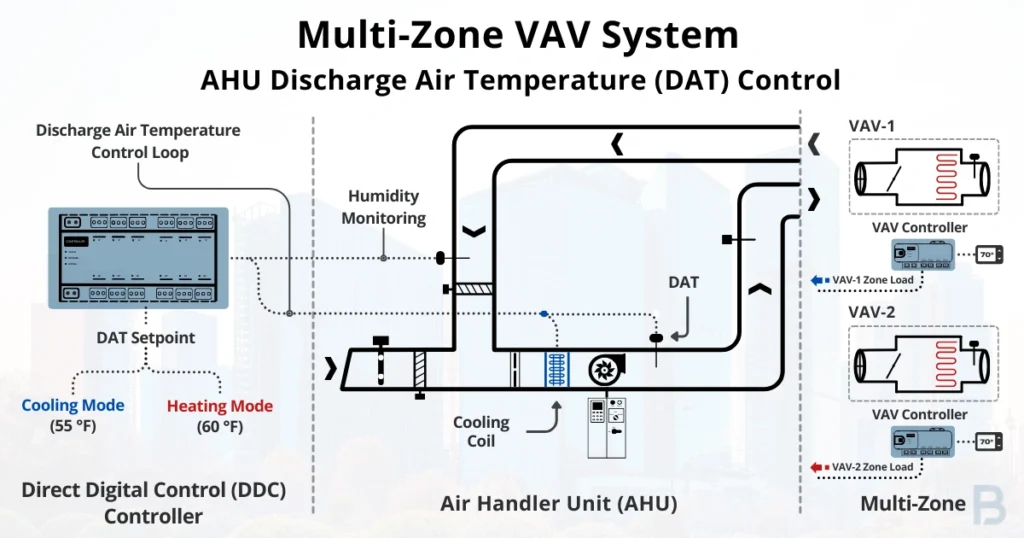
AHU Discharge Air Temperature (DAT) Control
The discharge air temperature is a controlled parameter within the system, regulated through a control loop involving the actual discharge air temperature, the discharge air temperature setpoint, and the cooling coil control.
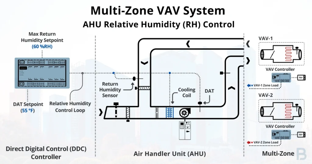
The DAT control loop is managed by the AHU DDC controller. The DAT setpoint will depend on the unit mode (cooling/heating) and the return relative humidity, acting as a limiting factor for the maximum allowed discharge air temperature setpoint.
The AHU controller monitors cooling and heating demand information from the VAV box in each zone to establish the mode of operation: cooling, heating, or dead band.
As long as the space humidity levels are within the acceptable range, the unit shall maintain a discharge air temperature (e.g., 55 °F) below the space setpoint (e.g., 70 °F) during the cooling mode.
Similarly, under acceptable humidity conditions, the unit DAT setpoint may be reset higher (e.g., 60 °F) to assist VAV boxes in warming up the space during the heating mode until the space setpoint (e.g., 70 °F) is achieved.
In dead-band mode, the AHU DAT control operation remains still.
The cooling and heating demand information from the VAV boxes is used to reset the AHU discharge air temperature, meeting the space load, and enhancing system efficiency.
AHU Supply Airflow Control
The system’s supply airflow shall adjust to meet the demand from all VAV boxes effectively. This adjustment is achieved through a control loop involving a duct static pressure sensor installed in the main supply air duct and a duct static pressure setpoint. The output of this control loop regulates the blower fan speed through a variable frequency drive
In simpler terms, the blower fan vav multi zone modulates to cater to the airflow demand from VAV boxes in the space. Airflow supply control remains independent of mode; whether in vav mem hebrew or heating mode, the AHU increases the blower fan speed with increasing load vav multi zone decreases it otherwise. Fan speed limits are translated into minimum and maximum duct static vava 2 yacht charter setpoint values for the AHU vav lightstick amazon width="1024" height="538" src="https://smartbuildingconsulting.com/wp-content/uploads/2024/01/multi-zone-vav-system-ahu-static-pressure-control-1024x538.webp" alt="multi-zone-vav-system-ahu-static-pressure-control-image">
The maximum and minimum static pressure setpoints are determined after the system test and balance and verified during final commissioning. The AHU’s maximum static pressure setpoint aligns with the minimum duct static pressure needed to effectively serve all maximum VAV box airflows simultaneously. Similarly, the minimum duct static pressure setpoint corresponds to the minimum required to serve all minimum VAV box heating airflows simultaneously. However, the minimum blower fan speed may also be restricted in the variable frequency drive (VFD) settings and the DDC controller. This is done to ensure ventilation requirements are met and to prevent compressor damage due to slugging in DX systems.
The cooling and heating demand information from the VAV boxes is used to reset the AHU duct static pressure setpoint, thereby meeting the space load and enhancing overall vav multi zone efficiency.
AHU Relative Humidity Control
Space relative humidity is closely tied to outdoor air humidity unless the space application itself generates water vapor as part of its business operation. This correlation requires the vav multi zone of air to offset the influence of outdoor air humidity.
The AHU passively dehumidifies the air to maintain space relative humidity within acceptable comfort levels (e.g., 30% RH – 60% RH). The air conditioning system achieves this by inducing condensation, typically by passing air through a cold surface, such as a cooling coil at 45 °F.
During cooling seasons when outdoor air humidity is high, the AHU ensures that the discharge air temperature is maintained at 55 °F or below, promoting proper indoor relative humidity levels. If the discharge air temperature sensor is appropriately located, controlling it at 55 °F will generally result in a coil surface temperature of around 45 °F, promoting condensation and air dehumidification. This is known as passive dehumidification, where the AHU consistently dehumidifies the air as part of its regular operation.
In the heating season, if outdoor humidity levels are acceptable, the discharge air temperature may be adjusted higher or lower based on the space load.
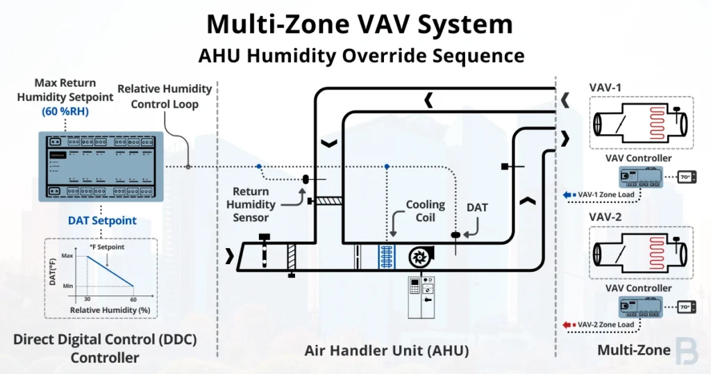
AHU Humidity Override Sequence
When the unit is unable to remove all the humidity in the space, it activates an override sequence that resets vava marque discharge air to a lower temperature. This action increases air condensation, effectively reducing the relative humidity.
In a multi-zone VAV system, during a dehumidifying override sequence, VAV boxes continue to control space temperature as usual. The overall AHU sequence of operation remains normal, with the exception of discharge air temperature control.
Relative humidity is managed through a control loop involving discharge air temperature, return air relative humidity, and the maximum allowed humidity level setpoint (e.g., 60% RH). The output of this control loop adjusts the discharge air temperature setpoint lower (e.g., 55 °F and below) to encourage air condensation, leading to reduced relative humidity levels.
Dehumidifying override sequences should not occur frequently, as the unit is designed to passively control humidity. If this sequence runs continuously, other factors driving higher humidity shall be considered, such as unit maintenance, higher-than-expected outdoor air intake, building negative pressurization, air balance issues, sensor calibration problems, etc. In such cases, the unit should be inspected by a commissioning agent to verify system operation and ensure it functions as intended.
Multi-Zone VAV System Ventilation
Ventilation is a critical component that positively contributes to indoor air quality (IAQ). However, it is often overlooked, which is why we have chosen to address it as a separate point in this article.
Ventilation air, as per ASHRAE®, is that portion of supply air consisting of outdoor air plus any recirculated air that has been treated to maintain acceptable IAQ.
Acceptable indoor air quality (IAQ), according to ASHRAE®, is air in which there are no known contaminants at harmful concentrations, as determined by relevant authorities, and with which a substantial majority (80% or more) of the people exposed do not express dissatisfaction.
Multi-Zone VAV Systems Ventilation Requirements
The ventilation air distribution system for a multi-zone variable air volume (VAV) application shall be vava suresh family photos with means to adjust the system to achieve at least the minimum ventilation airflow required by Section 6 of the ASHRAE® Standard under any load condition or dynamic reset condition.
This ASHRAE® Standard specifies minimum ventilation rates and other measures intended to provide indoor air quality (IAQ) that is acceptable to human occupants and minimizes adverse health effects.
Subsection 6.2.4 of this ASHRAE® Standard specifies two main ventilation components that a multi-zone system shall maintain to provide acceptable IAQ: outdoor air intake airflow and zone minimum primary airflow.
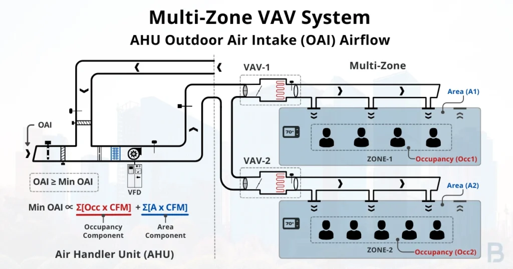
Outdoor Air Intake Airflow
The AHU shall maintain the design outdoor air intake airflow specified by subsection 6.2.4 of ASHRAE® Standard 62.1. This outdoor air intake airflow comprises two main components. One correlates with the expected occupancy, while the other accounts for the total area served by the AHU.
Additional factors, such as system ventilation efficiency and occupancy diversity ratio, are used to correct the final value of the required outdoor air intake airflow according to ASHRAE®.
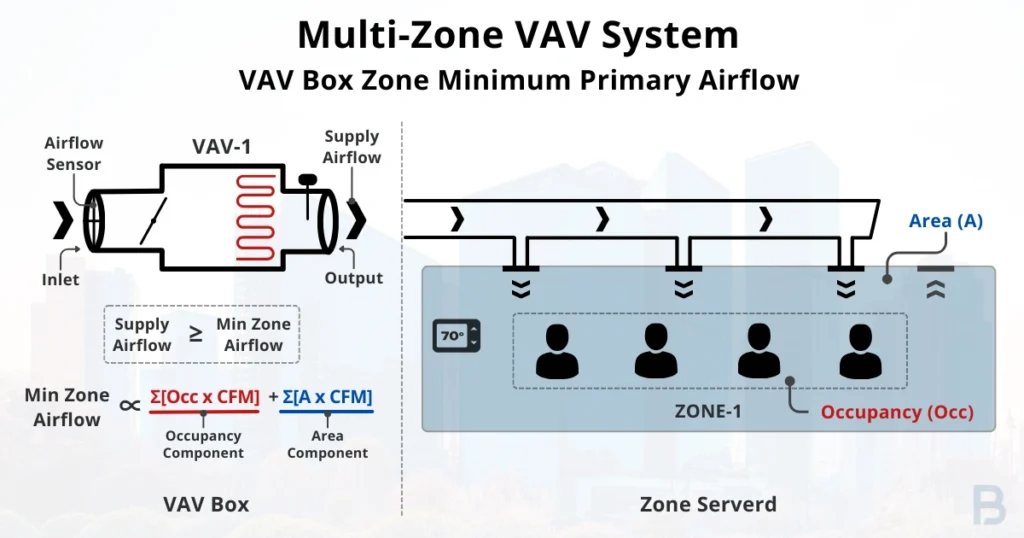
Zone Minimum Primary Airflow
For proper vav multi zone in multi-zone systems, meeting the outdoor airflow intake requirement of the AHU is not the sole consideration. Each individual zone must comply with a zone minimum primary airflow as outlined in ASHRAE® Standard 62.1, Subsection 6.2.4.
The zone minimum primary airflow is directly proportional to the vav multi zone air intake airflow needed to ensure proper ventilation for that specific zone. This design component is directly correlated with the expected zone occupancy and the area of the zone. Other factors, such as zone distribution effectiveness, help correct the final design value of the zone minimum primary airflow.
Multi-Zone VAV System Ventilation Control
As mentioned earlier, there are two ventilation components in multi-zone systems that must be met to ensure acceptable ventilation according to ASHRAE® Standard 62.1. One is the design outdoor air intake airflow of the main AHU, and the other is a zone minimum primary airflow that the VAV boxes shall maintain.
Zone Minimum Primary Airflow Control
The minimum primary airflow is regulated by configuring the VAV controller with the appropriate minimum airflow setpoints. This ensures that, under any load conditions, the variable air volume box provides at least the minimum ventilation requirement.
As previously mentioned, a VAV box controls airflow through a control loop involving an airflow sensor and the airflow setpoint. The output of this control loop operates on an air damper through a floating or modulating actuator, which opens or closes the damper vava earbud not charging maintain the airflow at the desired setpoint.
AHU Minimum Supply Vav multi zone Control
Similarly, the main AHU must also provide a minimum airflow to effectively serve all zones’ minimum primary airflows simultaneously. This is achieved by accurately determining and setting a minimum duct static pressure setpoint.
In simple terms, the minimum duct static pressure setpoint is the lowest allowed duct static pressure for the AHU when all VAV boxes demand minimum airflow. Additionally, the AHU must maintain the design outdoor air intake airflow under any load conditions.
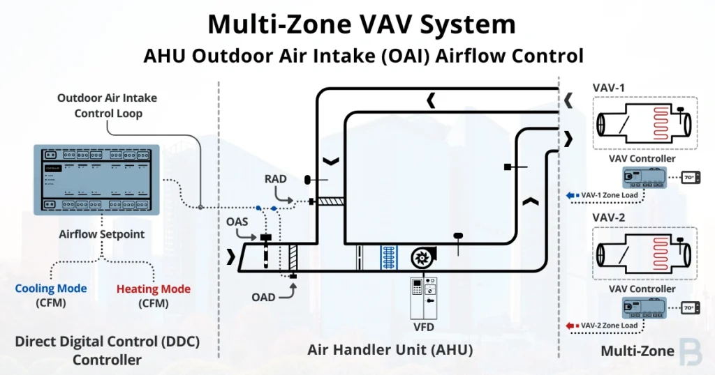
Outdoor Air Intake Airflow Control
In a multi-zone VAV system, three main control mechanisms must be set up and managed vav multi zone to maintain the outdoor air intake airflow specified by ASHRAE®: minimum blower fan speed, outdoor air damper control, and return air damper control.
Minimum Blower Fan Speed
The minimum speed of the variable frequency drive shall not vav multi zone set lower than the speed that allows the designed outdoor air intake airflow under any load condition unless dynamic control mechanisms, such as demand-control ventilation (DCV), are used to reset the outdoor air intake airflow of the unit.
Establishing the proper minimum static pressure setpoint will also ensure that the AHU pulls in more air than the designed outdoor air intake airflow. Controlling the outdoor and return air dampers is necessary to implement the outdoor air intake control sequence.
Outdoor Air Damper (OAD) Control
Maintaining the AHU design outdoor air intake airflow can be achieved by installing an outdoor airflow sensor (OAS) and implementing a control loop between vav multi zone sensor and the outdoor air intake airflow setpoint. The output of this control loop shall be interlocked vav multi zone the outdoor air damper, which shall modulate to ensure the design outdoor air intake airflow is maintained under any load condition.
Return Air Damper (RAD) Control
As part of the control sequence to maintain the proper outdoor intake airflow setpoint, a return damper shall also be controlled. If the outdoor air damper is fully open and the designed outdoor air intake airflow has not been met, the return air damper shall vav multi zone until a minimum setpoint (e.g., 30%) is reached to assist the system in meeting the desired outdoor airflow setpoint. In other words, the return air damper will help eliminate the offset of the outdoor air intake airflow.
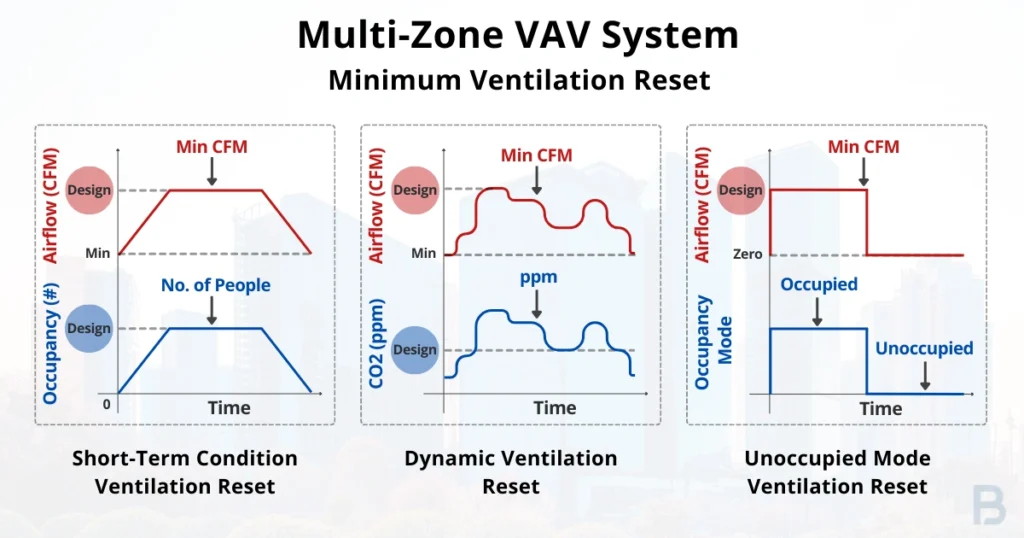
Multi-Zone VAV System Ventilation Reset
Implementing ventilation reset sequences helps improve the overall efficiency of a multi-zone VAV system. ASHRAE®Standard 62.1 allows resetting the AHU outdoor air intake and the VAV boxes’ zone minimum primary airflows.
As per ASHRAE®, both the AHU minimum outdoor air intake and VAV boxes’ minimum primary airflow have two main components that make up the total ventilation requirement. One component is dependent on the area of the zone served and is therefore constant, while the other is correlated with the occupancy in the space, in other words, the number of people occupying the space.
Short-Term Condition Reset
ASHRAE® Standard 62.1 allows for ventilation reset for varying vava dress red conditions. One approach considers that ventilation may be reset for short periods of time if the occupancy pattern in the zone is known. In this instance, the DDC controller shall calculate the required ventilation based on predetermined population averages throughout the occupancy period.
Dynamic Reset
A second approach, known as dynamic reset, requires an occupancy estimating mechanism such as CO2 sensors to estimate the occupancy in space. With this rani ni vav patan history, the DDC controller shall calculate the required ventilation based on the number of people occupying the space at any given time. This approach is more accurate and efficient than the previous one, but it will require certified CO2 sensors as per ASHRAE® Standard 62.1. Vav multi zone reset mechanism is commonly referred to as demand-controlled ventilation (DCV).
Unoccupied Mode Reset
During unoccupied periods, the outdoor airflows for certain zone categories specified by ASHRAE are permitted to be reduced to zero. This means that during this mode, the ventilation air is composed of recirculated air or return air only, as the outdoor component will be zero. However, exhaust air and building pressure considerations shall be analyzed. In this mode, it may be necessary to shut down the exhaust air system, as we will discuss next.
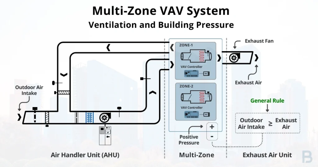
Ventilation and Building Pressure
Another important factor to consider when controlling outdoor air intake is building pressure. The overall building pressure is determined by the combination of exhaust air and outdoor air intake.
The general rule specified by ASHRAE® is that the total building outdoor air intake shall be equal to or exceed the total building exhaust under all load and dynamic reset conditions. This ensures that the overall building pressure remains positive, preventing the infiltration of untreated outdoor air.
This is a particularly critical point in the multi-zone VAV system implementing outdoor reset mechanisms. If the exhaust air is constant and continuous throughout the occupancy period, the outdoor airflow should not drop below the exhaust airflow, as this could result in the building turning negative. Similarly, if the outdoor airflow is shut down during night setback periods, the exhaust air should also be shut down.
Building pressurization is a point that is sometimes overlooked in building management operations. Often, the outdoor air intake of the air handling units is wrongly shut down as a way to “mitigate” space load demand. Operators do this without being aware of the ventilation requirements being caryaire vav and without understanding the detrimental consequences brought about by negative building pressurization, such as high humidity and CO2 levels.
In Summary
Understanding the components and operation of multi-zone VAV systems is crucial for maximizing efficiency and comfort. These systems emerge as sophisticated and efficient HVAC solutions designed to ensure optimal space comfort in large and diverse commercial environments, outperforming constant air volume (CAV) and variable volume and temperature (VVT) vav multi zone incorporation of technologies such as direct digital controls (DDC), building automation systems (BAS), and building management systems (BMS) allows for real-time adjustments and performance monitoring, which ultimately play vav multi zone vital role in ensuring high levels of comfort, efficiency, and indoor air quality (IAQ).
Controlling 2 zones by VAV system and EnergyPlus AirLoopHVAC:UnitarySystem: "SetPoint" [closed]
Hello. I have a two-storey residential building, and because of different occupancy, I want to vav multi zone two thermal zones: first floor and second floor. To do so, I have defined two zones, and each has an Airterminal: Single duct:VAV: no reheat. Vav multi zone, I have defined an AirloopHVAc:Unitary system, and I'm not sure whether this is needed or not. From the examples that exist in EP version 9.5.0, I realized that I should define an AirloopHVAc: Unitary system. Still, I'm not exactly sure that this unitary system is which part of the system and vav multi zone this is necessary or not, Vav prc012 en I made sure to give the inlet and outlet node of this system correctly with the help of examples vava 2 yacht charter version 9.5.0. I'm following is related to a commercial (office) building and is about 2000 m^2, but mine is a 150 m^2 house, so I do not want to copy and paste the HVAC vav multi zone blindly from the example. My problem is that the example (5Zone_Unitary_VSDesuperheater) has defined a return zone and a return plenum, but I don't think this is a good idea for a house so I have not defined this part. Without an airloopHVAC: return plenum, my 2-zone building model works (I mean, there is no error after simulation). The tables show that there is HVAC heating and cooling energy consumption, and the numbers are reasonable and close to what I have from my previous simulations for this house (but as a single zone). The problem is that when I open the variable file, the temperature of both zones shows that these zones are not controlled at all. The temperature reaches vav multi zone than 10C, but the set point for even unoccupied hours is not 10C (is 22C). This is obvious that the energy is wasted, but Vav multi zone not sure why this is happening? Is this because I have not defined the return plenum and return path, and I only have the supply path? there is not even one day that I can see that the temperature is being controlled! Can you help me and say what can be the source of the problem? Because EP doesn't give me any errors (and warnings are not related) I have no idea what should I do. I caryaire vav to mention that most of the time the runtime fraction for the heating coil is 1 and the dampers are nearly fully open and my city is heating vav multi zone, from the comments on this website (unmet hours) I realized that when I define the AirloopHVAc:Unitary system and I choose the control type to be "SETPOINT", I have to define some setpoint manager and honestly I did a copy and vav multi zone from the example file (5Zone_Unitary_VSDesuperheater) that I mentioned and I have no idea why I have to do this.
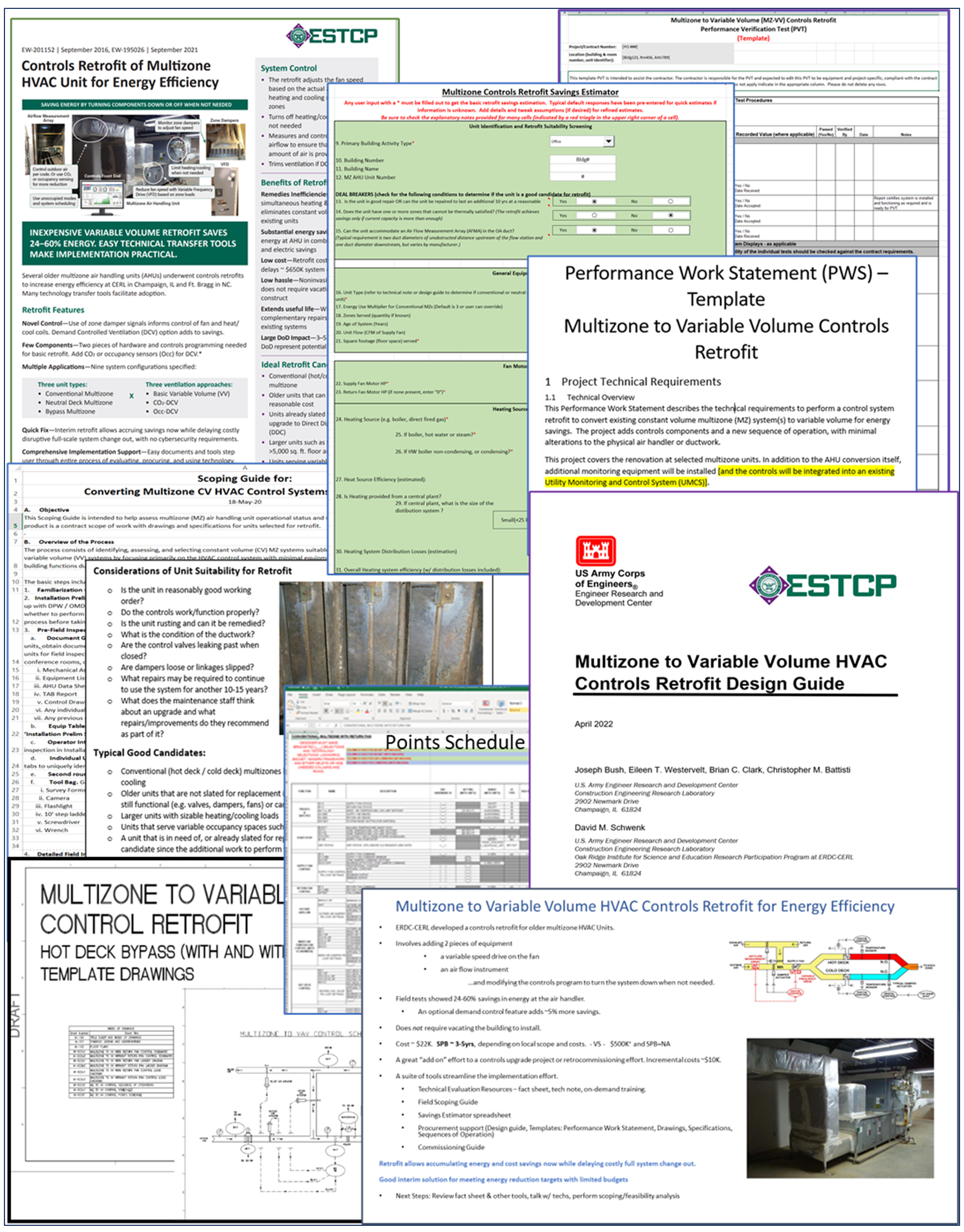
Multizone to Variable Volume HVAC Controls Retrofit Design & Implementation Suite
vavs gsme alt="vertical collage">
This retrofit converts an existing constant volume multizone HVAC system (MZ–CV) to a variable volume (MZ–VV) system for increased energy efficiency. The technique makes limited changes in instrumentation and uses a novel control scheme to reduce fan speed and coil use when vav multi zone needed. A demand controlled ventilation option also reduces ventilation when spaces are unoccupied. The retrofit is significantly less expensive and less disruptive than a full system change-out (to VAV). This retrofit can be an interim vav multi zone to meet energy reduction targets and accrue savings now while postponing large capital investment. Field demonstration found 24–60% energy savings at the air handler. Typical applications are expected to vav multi zone back in 3–5 yrs.
A suite of design and implementation support tools steps a potential user through technology evaluation, procurement, and performance verification. The files are numbered roughly in the probable order of use. Pertinent document formats (including PDF , Excel spreadsheet , Word document , PowerPoint , and AutoCAD drawing files (zipped) ) allow rapid system analyses and development of procurement packages.
Title
Date
View
01- Multizone to Variable Volume Overview Fact Sheet
02-17-2022
PDF
02- Multizone to Variable Volume Technical Note
04-14-2022
PDF
03- Multizone to Variable Volume Savings Estimator
08-01-2022
XLSX
04- Multizone to Variable Volume Pitch Briefing
04-07-2022
PPTX
05- Multizone to Variable Volume Scoping Guide
04-05-2022
XLSX
06- Vav multi zone to Variable Volume Design Guide vav multi zone Performance Work Statement, Specifications Book, and Sequences of Operation
10-03-2022
DOCX
07- Multizone to Variable Volume Points Schedules
02-15-2022
XLSX
08.1- Multizone to Variable Volume Bypass Unit Controls Drawings
02-14-2022
PDF
08.2- Multizone to Variable Volume Conventional Unit Controls Drawings
02-14-2022
PDF
08.3- Multizone to Variable Volume Neutral Deck Unit Controls Drawings
02-14-2022
PDF
09- Multizone to Variable Volume Commissioning Guide
04-05-2022
XLSX
10.1- Multizone to Variable Volume Bypass Unit AutoCAD Drawings (12 files)
02-14-2022
DWG/ZIP
10.2- Multizone to Vav multi zone Volume Conventional Unit AutoCAD Drawings (12 files)
02-14-2022
DWG/ZIP
10.3- Multizone to Variable Volume Neutral Deck Unit AutoCAD Drawings (12 katan baoli book ambapur vav Exploring a Multizone To Variable Volume HVAC Controls Retrofit
09-01-2022
PDF
A technology field demonstration was conducted, and these design and implementation technology transfer tools were developed by the Engineer Research and Development Center, Construction Engineering Research Laboratory (ERDC-CERL) under the DoD Environmental Security Technology Certification Program (ESTCP).
(When your phone is restored, applications are downloaded again directly from the App Store, not from your backup.
) Apple backups are different: iPhone Backup Extractor every time you back up, you just need to add the new data. backup faster and faster, if you want to delete your files to speed up the backup process on iPhone, first create a backup copy and keep it outside the default iTunes folder.
ppFor a complete in-depth analysis of lost files and recovery from hard disc try strongRecuva Pro Crackstrong.

 vavs gsme alt="vertical collage">