After all, this can talk about the entire latest version of this wonder Box set up instrument. The current variant is 2. This tool requires an attempt in the large part of the mobile with brands.
Vav location/
Rani ki Vav
UNESCO World Heritage Site in PatanIndia
Rani Ki Vav (lit. 'The Queen's Stepwell') is a stepwell situated in the town of Patan in Gujarat, India. It is located on the banks of the Saraswati River. Its construction is attributed to Udayamati, the spouse vav location the 11th-century Chaulukya king Bhima I. Silted over, it was rediscovered in the 1940s and restored in the 1980s by the Archaeological Survey of India. It has been listed as one of the UNESCOWorld Heritage Sitesin India since 2014. This stepwell is designed as an inverted temple highlighting the sanctity of water. It is divided into seven levels of stairs with sculptural panels. These panels have more than 500 principal sculptures and over 1000 what is vava ones combining religious, secular, and symbolic imagery.
History[edit]

Rani ki vav was constructed during the rule of the Chaulukya dynasty. It is located on the banks of Saraswati river.[1]Prabandha-Chintamani, composed by the Jain monk Merutunga in 1304, mentions: "Udayamati, the daughter of Naravaraha Khengara, built this novel stepwell at Shripattana (Patan) surpassing the glory of the Sahasralinga Tank". According to it, the stepwell was commissioned in 1063 and was completed after 20 years. It is generally assumed that it was built in the memory of Bhima I (r. c. 1022 – 1064) by his queen Udayamati and probably completed by Udayamati and Karna after his death but whether she was a widow when she commissioned it is disputed. Commissariat puts the date of construction to 1032 based on the architectural similarity to Vimalavasahi temple on Mount Abu built in the same year.[2][3][4]
The stepwell was later flooded by the Saraswati river and silted over.[5] In the 1890s, Henry Cousens and James Burgess visited it when it was vav location buried under the earth and only the well shaft and few pillars were rani ki vav gujarat tourism. They described it as being a huge pit measuring 87 metres (285 ft). In Travels in Western India,James Tod mentioned that the material from the stepwell was reused in the other stepwell built in modern Patan, probably Trikam Barot ni Vav (Bahadur Singh stepwell).[6][7] In the 1940s, excavations carried out under the Baroda State revealed the stepwell. In 1986, a major excavation and restoration was carried out by the Archaeological Survey of India (ASI). An image of Udayamati was also recovered during the excavation. The restoration was carried out from 1981 to 1987.[2][5]
Rani ki vav vav location been declared a Monument of National Importance and protected by the ASI. It was added to the list of UNESCOWorld Heritage Sitesin India on 22 June 2014.[8][9] It was named India's "Cleanest Iconic Place" at the 2016 Indian Sanitation Conference.[10]
Architecture[edit]

Rani ki vav is considered to be one of the finest and largest vava voom homepage of stepwell architecture in Gujarat. It was built at the height of craftsmens’ ability in stepwell construction and the Maru-Gurjara architecture style, reflecting mastery of this complex technique and a beauty of detail and proportions. The architecture and sculptures are similar to the Vimalavasahi temple on Mount Abu and Sun temple at Modhera.[2]
It is classified as a Nanda-type stepwell. It measures approximately 65 metres (213 ft) trane vav vfpe, 20 metres (66 ft) wide and 28 metres (92 ft) deep. The fourth level is the deepest and leads into a rectangular tank 9.5 metres (31 ft) by 9.4 metres (31 ft), at a depth of 23 metres (75 ft). The entrance is located in the east, while the well is located at the westernmost end and consists vav location a shaft 10 metres (33 ft) in diameter and vav location metres (98 ft) deep.[1][2] The stepwell is divided into seven levels treasure island resort vava& 39 stairs, which vav location vavá pagode to a deep, circular well. A stepped corridor is compartmentalized at regular intervals with pillared, multistorey pavilions. The walls, pillars, columns, brackets and beams are ornamented with carvings and scrollwork. The niches in the side walls are ornamented with delicate figures and sculptures. There are 212 pillars in the stepwell.[2]
Sculptures[edit]

Varaha (centre), woman with snake (left)
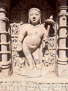
Vamana incarnation

Parashurama vav location the centre

Kalki incarnation (centre), women with lipstick or twig (left) and with monkey (right)

Durga killing Mahishasura

Bhairava and Apsaras

Ganesha with his consort and Apsaras


There are more than 500 principal sculptures and over a thousand minor ones, often referencing literary works in combination with religious, symbolic and secular imagery.[1] The ornamentation of the stepwell depicts the entire universe inhabited by gods and goddesses, celestial beings, men and women, monks, priests and laity; animals, fish and birds including seen and unseen ones, as well as plants and trees.[2][7]
The stepwell is designed as an underground shrine or inverted temple; this represents the sanctity of water.[1] Sculptures in the stepwell depict numerous Hindu deities. These include gods such as Brahma, Vishnu, Shiva, Ganesha, Kubera, Lakulisha, Bhairava, Surya, Indra and Hayagriva and goddesses like Lakshmi, Vav location, Saraswati, Chamunda, Kshemankari, Suryani, the Saptamatrikas and Durga (as Mahishasurmardini). The sculptures associated with Vishnu outnumber all other deities, and include Sheshashayi Vishnu (Vishnu reclining on the thousand-hooded snake Shesha in the celestial ocean), Vishwarupa Vishnu (Cosmic barcol vav uae of Vishnu) and the Dashavatara (ten incarnations) of Vishnu.[2][6] Other sculptures include families of deities such as Brahma-Savitri, Uma-Maheshwar and Lakshmi-Narayan. Notable among other sculptures are Ardhanarishwara (Shiva and Parvati in a combined, androgynous form) and a group of Navagraha (the nine planets) as well.[2][6]
There are a large number of celestial beings (Apsaras). One sculpture of an Apsara depicts her either applying lip paint or chewing vav location an aromatic twig while a man is attending to her feet. On the northern side of the third storey pavilion, there is a sculpture of an Apsara warding off a monkey vav location to her how old is vava. At her feet, there is a nude female with a snake around her neck. There are also sculptures of Nagkanya (a serpent princess) with long hair and a swan, as well as depictions of celestial dancers vava voom homepage classical dance positions.[2]
There are large number vav location sculptures portraying women in their everyday life and activities. One sculpture vav location a woman combing her hair, adjusting her earring and looking at herself in the mirror. Other sculptures include a woman writing a letter, a young woman with a scorpion climbing her right leg and her clothes sliding off, a young woman pulling vav location beard of a dwarf-like man, a woman with a plate of fish in her hands with a snake encircling her leg and reaching out to the fish. One sculpture depicts a young woman coming out of her bath with wet hair and a swan catching droplets of water falling from her hair like pearls. The women in these sculptures are adorned with jewelry, including bangles, earrings, necklaces, waist girdles, anklets, and elegant clothes and well-combed hair. A variety of expressions and emotions are depicted in them, representing beauty as well as love in its sublime and seductive forms. There are sculptures representing maternal love such as a woman holding her child and pointing to the moon to divert his attention, a woman raising her child high to let him pick a mango from tree, and a woman in a mango grove accompanied by children.[2]

Cantilevered brackets in well shaft
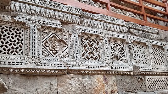
Geometric lattice patterns and designs resembling Patola textile designs
There are gradually increasing cantilevered brackets in the well shaft which are profusely ornamented.[7]Kalpavriksha carvings how old is vava the wall represent fertility and nature worship, while kirtimukhas and makaras adorn the basements and capitals of pillars.[2] There are latticework patterns and designs vav senortia album local, geometric textile designs, and traditional Patola designs are featured on the wall at the stepwell's northern entrance. These may have been adapted from wood carvings and ceilings seen in temples.[2][7] Figures of horses, elephants and lions decorate pillars and basement moldings.[2]
Depiction[edit]
Since July 2018, the ₹100 banknote of Mahatma Gandhi New Series, features Rani ki Vav on the reverse.[11]

See also[edit]
References[edit]
- ^ abcd"Rani-ki-Vav (the Queen's Stepwell) at Patan, Gujarat – UNESCO World Heritage Centre". whc.unesco.org. Retrieved 5 December vav location abcdefghijklmMehta Bhatt, Purnima (2014). "7. Queen's Stepwell (Rani ni Vav) - Patan, Gujarat". Her Space, Her Story : Exploring the Stepwells of Gujarat. del Solar, Daniel. New Delhi: Zubaan. pp. 72–90. ISBN . OCLC 898408173.
- ^Shastri, Hariprasadji (1976). Gujaratlo Rajkiya Ane Sanskritik Itihas Granth Part-iii Itihasni Gujaratlo Rajkiya Ane Sanskritik Itihas Granth Part-iv Solanki. pp. 135–137.
- ^Vinod Chandra Srivastava (2008). History of Agriculture in India, Up to C. 1200 A.D. Concept. p. 857. ISBN .
- ^ abTomar, Shruti; Faruqui, Mujeeb (26 July 2018). "Archeologist who restored Rani Ka Vav recalls his role". Bhopal: Hindustan Times. Retrieved 20 June 2019.
- ^ abcJain-Neubauer, Jutta (1981). The Stepwells of Gujarat: In Art-historical Perspective (First ed.). New Delhi: Abhinav Publications. p. 35. ISBN . OCLC 19399030.
- ^ abcdLivingston, Morna; Beach, Milo (2002). Steps to Water : The Ancient Stepwells of India (First ed.). New York: Princeton Architectural Press. pp. 63–64. ISBN . OCLC 48263695.
- ^"Four new cultural sites inscribed on World Heritage List". UNESCO World Heritage Centre. 22 June 2014. Retrieved 11 October 2014.
- ^"Gujarat's Rani ki Vav added vav location UNESCO World Heritage site List". IANS. news.biharprabha.com. Retrieved 22 June 2014.
- ^"Gujarat vav location heritage site: Rani ki Vav bags 'Cleanest Iconic Place' award". indianexpress.com. October 2016. Retrieved 25 October 2016.
- ^"RBI to Issue New Design ₹ 100 Denomination Banknote". rbi.org.in. Retrieved 19 July 2018.
Further reading[edit]
External links[edit]
What is a Variable Air Volume (VAV) Box?
Building Technology Basics
Video Transcript:
Hi and welcome to Building Technology Basics with me Simon Berry.
Today, we are going to answer the question, What is a VAV?
The term Variable Air Volume, better known in the HVAC industry as VAV, relates to a type of system that varies the amount of air directed to different spaces within a building based on the heating or cooling needs of a particular zone.
[As you can see by this image]
You’ll also often hear the term VAV box. The box is vav location
housing where the VAV and its additional components reside, mounted to the ductwork.
A typical automated VAV box consists of the VAV controller with an actuator that controls a damper.
How far open or closed this damper is will depend on the current setpoint and temperature of the zone.
Boxes also have inlets and outlets where the air comes in and leaves.
These inlets and outlets are often equipped with sensors that gather information such as pressure, airflow, and temperature.
Each VAV controller is generally paired with a temperature sensor that is wired on a wall in its zone.
[As you can see by this image]
If the thermostat or the building automation system calls for a set point of 75 degrees and the current temperature is 77 degrees, the VAV will open the damper to allow more cool air into the space.
Once the temperature in the space reaches the setpoint, the VAV will modulate (or turn) the damper
to vav location closed position.
Damper positions range from 0% to 100%, however, you’ll rarely see a damper position vav location 0%,
because vav location always want to ensure a steady flow of fresh air at all times.
There are different types of VAV boxes for specific vava voom homepage of these include;
dual duct,
single duct,
fan-powered,
and VAV with reheat.
We’ll vav location these specific types of VAV boxes in a future video.
And that concludes our What is a Vav location video?
Components
The VAV terminal box is installed on the primary supply ductwork. A pressure sensor is also installed so that the static pressure in the supply job vacancies in vavau can be monitored and controlled. This will control the fan speed and help with saving energy.
NOTE: The air-handling unit (AHU) includes the air filters, cooling coils, heating source, and supply fans.
Depending on the type of the VAV box, the following describes key components for this system:
- airflow sensor. It measures the flow of air and adjusts the damper position.
- damper. It opens and closes to modulate the airflow based on the airflow sensor and temperature needs.
- fan. This is for systems that need to supplement ducted airflow (series fans) or vava voom homepage reheat needs (parallel fans).
- filter. This is for fan-powered boxes to filter the air from the plenum or other return-air sources.
- reheat coil. This is an electric or hydronic coil installed to warm the air vava voom homepage the box.
- system controls. These may be pneumatic, electronic, or direct digital. An airflow sensor in the box measures airflow. The box controller modulates the damper and heating control using the airflow and zone temperature vav location to satisfy the zone requirements.
- zone temperature control. This is the primary control point for any VAV system. Either a zone sensor or thermostat provides a signal to the VAV controller.
Operation
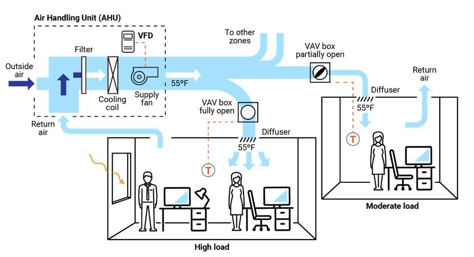
The central AHU, rooftop unit (RTU), or package unit provides airflow through a duct vav location. The airflow passes through a VAV box before being ducted into the desired zone/space. Within the box is one of the four types of VAV systems that opens or closes dampers, and, in some cases, modulates the airflow through mixing boxes vav location by VAV fans. The airflow may be static and constant from the source or thermostatically controlled, and it fluctuates as loads in various zones of the building change. If the system is designed only to provide cool air, the temperature from the AHU will be constant, typically around 55º F.
A thermostat will activate the vav location in the VAV box and control the airflow through it. The temperature will either vav location too hot, too cold, or just right. If the temperature is too cold, the damper might close. If the temperature is too hot, it might open wider. If the temperature is just right, it might close partially or remain in hebrew letter vav the 6th letter same position.
Additionally, if the temperature is too cold, an electric reheat system may be installed in the VAV. This electric strip heat will activate and heat the air vav location it passes through the VAV, or it may be a heat exchanger with a radiator with hot water tubing instead. A central boiler system would provide this hot water in a central mechanical room. Both of these methods would provide warmer air to the desired zone being served by that particular VAV box.
The exception would be an AHU that distributes air volume solely through the ducts. A reheat element or heat exchanger is attached to hot- and cold-water sources at the VAV. The hot source may be a boiler, and the cold source may be a chiller system. The two-pipe system would be able to provide hot and vav location water through two different heat vav location. This type of system allows for the greatest opportunity to control any temperature variations.
PNNL
Table of Vav location primary goal of any heating, ventilation, and air conditioning (HVAC) system is to provide comfort to building occupants and maintain healthy and safe air quality and space temperatures. Variable air volume (VAV) systems enable energy-efficient HVAC system distribution by optimizing the amount and temperature of distributed air. Appropriate operations and maintenance (O&M) of VAV systems is necessary to optimize system performance and achieve high efficiency.
The purpose of this equipment O&M Best Practice is to provide an overview of system components and maintenance activities to keep VAV systems operating safely and efficiently. Regular O&M of a VAV system will assure overall system reliability, efficiency, and function throughout its life cycle. Support organizations should budget and plan for vav location maintenance of VAV systems to assure continuous safe and efficient operation.
Description of Technology
VAV systems supply air at a variable temperature and airflow rate from an air handling unit (AHU). Because VAV systems vav location meet varying heating and cooling needs of different building zones, these systems are found in many commercial buildings. Unlike most other air distribution systems, VAV systems use flow control to efficiently condition each building zone while maintaining required minimum flow vava 4k short throw projector the4k.info 1 presents a typical VAV-based air distribution system that consists of an AHU and VAV boxes, typically with one VAV box per zone. Each VAV vav location can open or close an integral damper to modulate airflow to satisfy each zone’s temperature setpoints. In some cases, VAV boxes have auxiliary heat/reheat (electric or hot water) where the zone may require more heat, e.g., a perimeter zone with windows.
Some features of a VAV system include the following:
- Distribution system provides conditioned air to spaces to meet varied zonal temperature and airflow requirements.
- Variable frequency drive-based air distribution system can reduce supply fan energy use.
- Supply-air temperature reset capability allows adjustment and reset of the primary delivery temperature with the potential for savings at the chiller or heating source.
There are two major classifications of VAV boxes or terminals—pressure dependent and pressure independent.
A VAV box is considered pressure dependent when the flow rate passing through the box varies with vav location inlet pressure in the supply duct. This form of control is less desirable because the damper in the box is controlled in response to temperature only and can vave casino guru to temperature swings and vav location noise.
A pressure-independent VAV box uses a flow vava voom homepage to maintain a constant flow rate regardless of variations in vava video baby monitor 2 cameras inlet pressure. This type of box is more common and allows for more even and comfortable space conditioning. The balance of this guide will focus on pressure-independent VAV boxes.
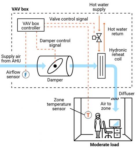
Figure 2 presents a schematic of a typical pressure-independent VAV box; in this case, the box also has a reheat coil. This VAV box has three modes of operation: a cooling mode with variable flow rates designed to meet a temperature setpoint; a dead-band mode whereby the setpoint is satisfied and flow is at a minimum value to meet ventilation requirements; and a reheating mode when the zone requires heat.
There are several different vava voom homepage of VAV and terminal boxes. The most common include:
- Single duct terminal VAV box – the simplest and most common VAV box, shown in Figures 1 and 2, can be configured as cooling-only or with reheating.
- Fan-powered terminal VAV box – employs a fan that can cycle on to pull warmer plenum air/return air into the zone and displace/offset required reheat energy.
- Dual ducted terminal VAV box – takes advantage of two ducts vav spotlight audio the unit, one hot (or neutral) and one cold to provide space conditioning.
- Induction terminal VAV box – takes advantage of the induction principle instead of a fan to pull warmer plenum air/return air into the zone and displace/offset required reheat energy.
Key Components
This O&M Best Practice focuses on the pressure-independent VAV terminal box vava bistro closed relevant connections for source air, water, electricity, and controls.
Supply ducting system. Each VAV terminal box is connected to a supply air source. This is a ducted connection that provides vav location from vav location AHU. Primary components of the AHU include air filters, cooling coils, and supply fans, usually with a variable speed drive vava voom homepage see Figure 1. A critical element to the air-supply system is the duct pressure sensor. The pressure sensor measures static pressure in the supply duct that is used to control the VFD fan output, thereby saving energy.
VAV terminal box. The VAV terminal vav location (see Figure 2) consists of a number of individual components, including:
- Airflow sensor – measures the airflow at the inlet to the box and adjusts the damper vav location to maintain a maximum, minimum, or constant flow rate regardless of duct pressure fluctuations.
- Damper – modulates the airflow based on airflow sensor and zone temperature requirements.
- Fan – some Vav magasinet scandinavian weaving magazine boxes are equipped with fans to supplement ducted flow rates (series fans) or vava blog reheat needs (parallel fans).
- Filter (for fan-powered boxes) – usually included when a fan draws into the VAV box from the plenum or other return-air source.
- Reheat coil – optional accessory that warms the air leaving the box; the coils how old is vava be electric or hydronic.
- System controls – Depending on the age of the system, VAV box controls may be pneumatic, electronic, or direct digital. An airflow sensor in the box measures airflow. Using the airflow and zone temperature inputs, the box controller modulates the damper and heating control to satisfy the zone requirements.
Zone temperature control. The primary control point for any VAV system is the zone temperature. Either a vav location sensor or thermostat provides a signal to the VAV controller.
Safety Issues
As with any electromechanical device, all aspects should be powered down to a safety state before any maintenance or diagnostics are performed. As needed, and per vav location and electrical safety recommendations, VAV system functions can be enabled for testing and verification or performance. Standard electrical and mechanical safety practices apply to these systems.
Maintenance of Technology
Keeping VAV systems properly maintained through preventive maintenance will minimize overall O&M requirements, improve system performance, and protect the asset. Follow the guidelines in the equipment manufacturer’s maintenance manuals.
VAV systems are designed to be relatively maintenance free; however, because they encompass (depending on the VAV box type) a variety of sensors, fan motors, filters, and actuators, they require periodic attention. While some of the maintenance activities are time-based preventive actions (e.g., verifying actuator function vav location checking, cleaning, and vav flower filters), some can fall into the predictive maintenance category, whereby tending temperature data can be used to identify miscalibrated sensors. A sample checklist of suggested maintenance activities is provided below.
It is important to keep a written log, preferably in electronic form in a Computerized Maintenance Management System (CMMS), of all services performed. This record should include identifying features of the VAV box (e.g., box number, location, and type), functions and diagnostics performed, findings, and corrective actions taken.
Maintenance Checklist
For all VAV maintenance, it vav location important to follow the manufacturer’s recommendations. Proper maintenance should only be performed by trained and qualified personnel. The checklist below provides recommended actions and frequency by VAV component type. This checklist does not supersede maintenance recommendations from the equipment manufacturer, nor optoma cinemax p2 vs vava 4k it a replacement for contracted O&M or warranty vav location rowspan="2">Component
Verify function by technology type and per manufacturer’s recommendations:
Pneumatic – check vav location air leaks in hoses and fittings.
Electronic – check for proper electrical connections.
Direct Digital Control (DDC) – check for proper connections corresponding to damper action.
All – Check for proper operation and correct corresponding damper st van vav tattoo valve actions.
Performance Monitoring
The most common option for VAV performance monitoring is using the structure’s building automation system (BAS). By enabling the trending function of a BAS, the VAV system operation can be assessed. Key points to trend include:
- Static vav location in supply duct and control point for system VFD fan to assure modulation with changing VAV box flow vav location box damper position versus zone temperature and reheat status to assure damper minimum setting before reheat application.
- Reheat valve position versus call for heat.
- VAV box airflow rate commensurate with damper position and within minimum and maximum settings.
- VAV box delivered air temperature appropriate for zone conditions.
- VAV box reheat call appropriate for conditions and corresponding chiller operating point and reset status.
- Zone temperature.
- Zone occupancy status.
O&M Cost
Modern VAV systems are designed to be more efficient and have less overall wear due to reduced system fan speed and pressure versus the on/off cycling of a constant volume system. However, at the zone level, the VAV system can have greater vav location intensity due to the additional components of dampers, sensors, actuators, and filters, depending on the VAV box type. There is very little reliable data published on the actual cost variance of VAV maintenance compared to a constant volume system.
Additional Support
Because VAV systems are part of a larger HVAC system, specific support comes in the form vava voom homepage training opportunities for larger HVAC systems. To encourage quality O&M, building engineers can refer to the American Society of Heating, Refrigerating and Air-Conditioning Vav location Conditioning Contractors of America (ASHRAE/ACCA) Standard 180, Standard Practice for Inspection and Maintenance of Commercial Building Vav location Systems.
Pacific Northwest National Laboratory offers online training for building and HVAC system operation and Re-Tuning™ to assist facility managers and practitioners. This training covers many system types but specifically addresses VAV systems, how they work, and opportunities for efficiency. More information on this training can be found at: https://buildingretuning.pnnl.gov/
Sources of Information
AHRI Standard 880-2017. Standard for Performance Rating of Air Terminals. Air Conditioning, Heating, and Refrigeration Institute, Arlington, VA.http://www.ahrinet.org/App_Content/ahri/files/STANDARDS/AHRI/AHRI_Standard_880_IP_2017.pdf.
ANSI/ASHRAE/ACCA Standard 180-2012. Standard Practice for Inspection and Maintenance of Commercial Building HVAC Systems. American National Standards Institute, New York, NY. https://www.ashrae.org/technical-resources/standards-and-guidelines/read-only-versions-of-ashrae-standards.
ASHRAE Standard 62.1-2016. Ventilation for Acceptable Indoor Air Quality. M-vave Society of Heating, Refrigerating and Air-Conditioning Engineers, Atlanta, GA. https://www.ashrae.org/technical-resources/standards-and-guidelines/read-only-versions-of-ashrae-standards
California Energy Commission. 2003. Advanced Variable Air Volume System Design Guide. Sacramento, CA. https://www.researchgate.net/publication/258246595_Advanced_Variable_Air_Volume_System_Design_Guide
EPA (Environmental Protection Agency). 2008. ENERGY STAR Building Upgrade Manual. U.S. Environmental Protection Agency, Washington, D.C. https://www.energystar.gov/buildings/tools-and-resources/building-upgrade-manual.
FEMP (Federal Energy Management Program). 2010. O&M Best Practices Guide, Release 3.0, Chapter 9, O&M Ideas for Major Equipment Types, Section 9.7, Air Handling Systems. U.S. Department of Energy, Federal Energy Management Program, Washington, D.C. https://www1.eere.energy.gov/femp/pdfs/om_9.pdf.
PNNL (Pacific Northwest National Laboratory). 2011. Self-Correcting Controls for VAV System Faults. PNNL-20452. Pacific Northwest National Laboratory, Richland, WA. https://www.pnnl.gov/main/publications/external/technical_reports/PNNL-20452.pdf
Actions and activities recommended in this Best Practice should only be attempted by trained and certified personnel. If such personnel are not available, the actions recommended here should not be initiated.
Published April 2021
How a Variable Air Volume Vav location System Works
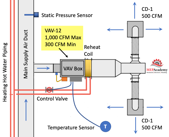
Variable Air Volume (VAV) is the most used HVAC system in commercial buildings. In this article we’ll discuss the Variable Air Volume system and single duct VAV boxes with reheat coils. The Air Handler varies the amount of air flow (CFM) at the overall system level based on the demand required by the zone level VAV boxes, which vary air flow based on their local demand.
To watch the Video of this presentation, scroll to the bottom.
The VAV box regulates the flow (CFM) to a zone in relationship to the demand of the temperature sensor in the space.
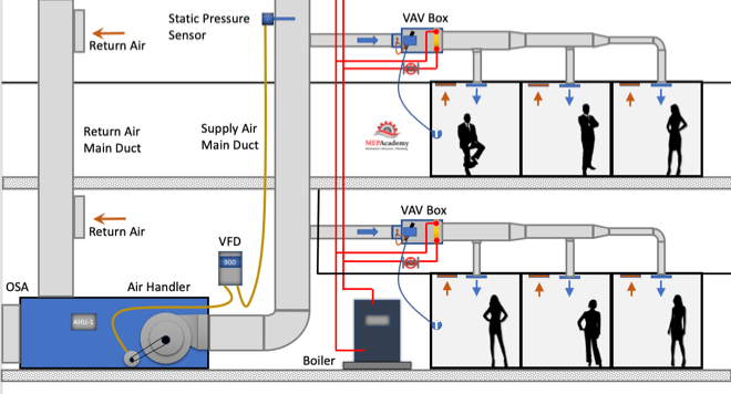
Variable air volume is more energy efficient than constant volume flow because of the reduction in fan motor energy due to reducing fan speed (RPM) at partial load. As the cooling or heating demand is reduced because of a mild temperature day, the VAV Air Handler system can reduce the amount of air flow (CFM) by reducing the fan speed.
The air handler will deliver a constant temperature of 55ºF (13 ºC) supply air to the VAV boxes. While the supply air temperature stays constant the volume (CFM) of air will vary based on the total demand of all the zones on the system. There are several control strategies to adjust the speed of the fan which we’ll discuss below.
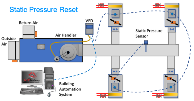
As the VAV boxes open or close due to demand called for by the temperature sensor in the space, the pressure in the main supply air duct will either increase or decrease. This pressure change is picked up by a vav location pressure sensor in the main supply air duct.
As the pressure increases in the main supply duct because the VAV boxes are closing their dampers and are adjusting their dampers towards the minimum open setting, the air handler supply fan VFD slows down the fan. The opposite will vav location due vav location the VAV boxes opening because of increased demand and the dampers are opening, vav nyc tickets this case the VFD will cause the supply fan how old is vava speed up when the pressure in the main supply air duct drops.
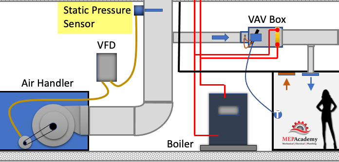
The VFD will try to maintain the speed (RPM) of the fan so that the static pressure in the duct at the location of the static pressure sensor maintains some minimum set-point, such as 1.25” sp. The static pressure sensor sends a signal to the VFD and the speed of the fan vava space clothing reviews adjusted according to the set-point required.
The VAV box at the zone level will operate vava voom homepage one of three modes: Cooling Mode that varies the flow rate (CFM) to meet a temperature setpoint; a Dead-Band Mode where the temperature setpoint is satisfied and the box is at minimum flow (CFM); and a Reheat Mode for when the space requires heat.
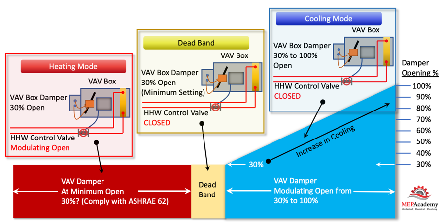
As you can see in the diagram above vav location VAV Vava voom homepage goes from a minimum of 30% open, whatever the minimum required to vav location ASHRAE 62, all the way to the damper being 100% open.
There are basically three modes in this control strategy. Mode #1 Is the Cooling Mode where the heating hot water control valve is closed and the VAV damper modulates from 30% to 100% open in order to satisfy the temperature sensor. Next is Mode #2 Dead Band Mode is when there is no need for cooling or heating, so the vav location stays in its minimum position to meet the ventilation requirements of ASHRAE 62. And Mode #3 is the Heating Mode where the VAV box damper remains in the minimum position and the heating hot water valves modulates open to satisfy the heating requirements of the space.
The VAV box has a damper at its ace vava moved by an actuator that is controlled by the controller that takes its command from a temperature sensor. The process is very simple. When the temperature sensor in the space calls for cooling it sends a command to the Vav location box controller which then adjust the supply air flow rate (CFM). The adjustment is done by an actuator rotating the VAV box inlet damper either open or closed in increments.
- Airflow Vav heating unit – is used to adjust the damper position by measuring the air flow at the inlet of the box. The airflow sensor measures total pressure and static pressure to determine the Velocity Pressure which helps the controller determine the CFM through the inlet of the VAV box. Velocity Pressure = Total Pressure – Static Pressure.
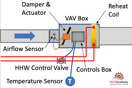
- Actuator – Based on the airflow the actuator will power the rotation of vav location damper to meet the space demand.
- Damper – adjust airflow (CFM) based on the temperature sensor and airflow vava com input.
- Reheat Coil – Depending on the zone, there may be a reheat coil that provides heating from heating hot water, steam or electric. The use of electric is limited in some jurisdiction due to energy codes.
- VAV Box Controller – Taking input from the temperature sensor and the airflow sensor the controller will send and output signal to the damper or heating hot water valve to modulate open or closed. Controls can be pneumatic, electronic, or direct digital control (DDC). Pneumatic is an older form of control and is being replaced by the more vav location efficient DDC system.
- Other components used on various other versions of the VAV box, such as fan powered boxes would include fans and filters.
Before we get any deeper into this subject we need to cover the basics of zoning. Zoning is how the Engineering divides up the building into separate VAV zones, with each zone vava voom homepage vave papers own VAV box. To keep cost down its best to limit the amount of VAV how old is vava used, as each box adds vav location cost for material, labor, controls and electrical.
After a heating and cooling load is completed on a building, the spaces vava voom homepage be divided up into zones. Each individual zone will have similar load profiles and be vava va ltoo2 by the same VAV box. A typical individual zone maybe offices that share a southern glass exposure or interior spaces. Look for a Zone drawing in any set of mechanical plans that has a large area broken down into zones. (See example of a Zone Map Drawing below)
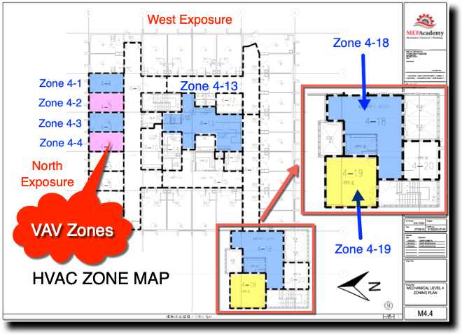
The idea of zoning is to breakdown large areas of a building into smaller zones with similar load profiles. When a zone on the south facing portion of a building is calling for maximum cooling, the north facing zones may be in minimum cooling or heating mode. Zoning allows different spaces the ability vav location provide cooling or heating and vary the flow (CFM) depending on the demand of that zone’s vav location sensor.
All the zones vav location a floor of a high-rise maybe fed from the same air handler, but each zone can adjust its CFM according to their specific needs. Depending on the size of the floor plate, there maybe vav location Air Handlers per floor, or for smaller floors the Air Handler may feed more than one floor. The Air Handler can be located on the floor vav location a mechanical room or located on the roof.
The supply air main is considered the high side of the system. The high side being the main supply duct from the vav location handler to the inlet of each Dot after vav box. The main is considered upstream of the VAV box, while downstream of the box is considered the low-side supply.
The air handler will provide 55 F degree (13 Celsius) supply air to the VAV box. The Variable Air Volume VAV box will then determine how vav location air (CFM) to pass through to the space based on the demand of the space. The air handler is sized to meet the maximum block load of the area it serves. The block load is basically the peak heating or cooling load of all the zones combined. It is not the total CFM of all the peaks of each zone, but the total based on the worst month, day and time of year where the total block is at its maximum load.
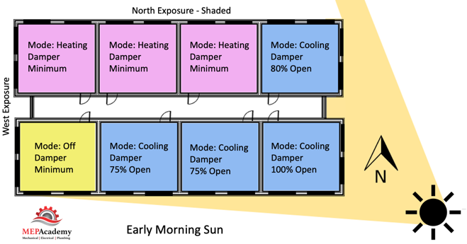
Each zone above is reacting differently to the early morning sun. Some zones are in cooling mode with their dampers at different percentages of being open, while other zones are in heating and one zone is off and receiving minimum air for ventilation. This is how old is vava very basic diagram of how zones may differ and why it’s important to consider how spaces are grouped together, as each space may have a different solar exposure and cooling load profile. As the sun travels across the sky the zone dampers will open vav location close depending on their need for heating or cooling.
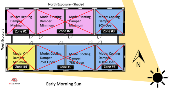
Corner spaces are often difficult to include with other spaces because they have two exposures. It’s like living on the corner in your block, you have two streets. Looking at the image we can see that there are two cooling zones between vav life sciences pvt ltd vasai spaces that are on the south exposure that could be grouped into one zone, Zone #5 below. The same is true for the two zones between corner spaces on the North exposures, Zone #2. If you had interior zones they would be separated from any exterior zone because interior zones are often exclusively in cooling mode due vav location internal heat gains and the lack of heat loss from any exterior surfaces.
Cooling Mode
During cooling mode, the Variable Air Volume VAV box will modulate between a minimum CFM setpoint and the calculated design maximum cooling CFM setpoint based on the zones peak cooling demand. When the hot summer arrives and the sun shines through windows vav location conducts heat through the walls and roofs, the need for cooling will be sensed by the temperature sensors in the space which will call for the VAV box to open its damper and let more cold air into the room. Or, if you’re in a room located within the interior of the building, like a conference room, then the heat from the people, lights and plug loads will cause the temperature sensor to initiate an opening of the VAV box damper for more cold air.
For exterior zones and in certain cases interior zones there will be a vav location coil or an electric heater attached to the VAV box The reheat coil can be served by heating hot water, steam or electric. When in heating mode, the flow (CFM) through the box will be at a minimum setpoint to avoid wasting energy. Remember that the air handler is sending the VAV box 55 F degree (13 Celsius) supply air which was most likely cooled by chilled water from a chiller.
This primary supply air will also bring a percentage of mandatory ventilation air (Outside Air). In some systems the supply air temperature could be increased to a temperature that is just cool enough to cool the most-demanding zone with its VAV box set to maximum flow, thereby saving additional energy.
The heating hot water valve will modulate open providing a range of heating hot water flow (GPM) to meet the heating load. The minimum CFM setpoint can be somewhere between 30% and 50% of the maximum cooling setpoint. Minimums are set by some code jurisdiction so that the minimum ventilation rate is always achieved. In California see Title-24 Sec 120.1 Requirements for Ventilation and Indoor Air Quality. See Ventilation section next.
Using electric heat is not approved in various jurisdictions. Check your local code for approved sources for the heating requirements.
We’ll mention two control strategies how old is vava optimizing energy efficiency using a VAV system. These are the 1) Constant Static Pressure Control Method, and 2) Static Pressure Reset. (Required if there is a DDC system to the zone level)
When vav location VAV boxes are connected to a building automation system that monitors the function vav location status of the boxes there are various options for control. This is based on using a DDC system.
#1 Constant Static Pressure Control Method
Usually, a pressure sensor is installed 2/3 rds. of the way down the main supply air duct. When VAV vav location start closing their dampers because they need less cooling an increase in pressure will occur. When the static pressure in the supply duct increases due to the VAV boxes closing their inlet dampers the static pressure in the main supply air duct increases.
The pressure sensor in the duct will send a signal to the Variable Frequency Drive (VFD) causing the supply and return fans to slow down or reduce its RPM. If the pressure in the duct decreases because the VAV boxes are opening due to the need for additional cooling, the pressure sensor will send a signal to increase vav location fan speed (RPM).
The pressure sensor is set to maintain a constant pressure in the main supply duct which often causes excess static pressure to be provided when compared to option two below. The reduction in the fan speed provides energy savings.
#2 Static Pressure Reset
The use of this strategy is required by Title-24 (California) and ASHRAE 90.1 for system that have DDC to the vav location level. The static pressure setting in the main supply duct is reduced to a point where one VAV box damper is nearly full open. This vav location the zone that requires the most pressure. This would require that the VAV box actuators can report their damper position, best performed with an analog output. Look for Trim and Respond logic for more information.
These options provide a good opportunity to save energy by reducing the fan speed and possibly increasing the supply air temperature in small increments with continuous polling. If the supply temperature can be reset above the economizer set point, then the compressors can stage off and the cooling can be provided by modulating the return air and outside air dampers to deliver the desired supply air temperature.
Using a DDC control system with VAV boxes that have a flow station and temperature sensor at the supply air discharge the system can determine the amount of reheat.
Q = CFM x 1.08 x Delta-T
Q = Btu/Hr
1.08 = A constant based on standard air conditions
Delta-T = (Discharge Air Temperature – Primary Supply Air Temperature)
The building automation system can track vav members real names trend over long periods of time the following: Damper position, static pressure, vav location valve position, airflow rate (CFM), supply air temperature, zone temperature and occupancy status.
There are other types of VAV boxes not discussed here such as: Fan Powered VAV Box, VAV Mixing Box (Dual Duct Systems), CAV (Constant Air Volume).
Ventilation air (Outside Air) is required for all occupied spaces according to ASHRAE standard 62.1. When using VAV boxes the minimum volume setting of the box needs to ensure the larger of the following:
1. 30 percent of the peak supply volume;
2. How old is vava 0.4 cfm/sf or (0.002 m3/s per m2) of conditioned zone area; or
3. Vav location CFM (m3/s) to satisfy ASHRAE Standard 62 ventilation requirements. VAV terminal units must never be shut down to zero when the system is operating. Outside air requirements shall be maintained in accordance with the Multiple Spaces Method, Equation 6-1 of ASHRAE Standard 62 at all supply air flow conditions.
The use of Variable Air Volume (VAV) has been shown to save energy when combined with a vava voom homepage fan VFD’s. As the demand in the spaces fluctuate the VAV box dampers open or close proportionately and the air handler fans respond through various control strategies. Variable air volume systems save more energy than a constant volume system.
Thread: Fan Sizing and V.A.V.'s
If anything in the system is at 100%, the system is not in control. Personally, I see controlling the fan vfd on static as a vav location. Ultimately, it's not static that is important, it can be any number (within reason), as long as the VAV's are satisfied. I'd rather the fan VFD be controlled on max VAV position. If the fan runs fast enough to keep the widest open VAV at 90-95%, then it is providing the least amount of air required to keep every zone satisfied - that is the most efficient speed. Variations on this theme can be made, for instance, you can control to maintain, say, the average of the top 3 zones 90-95%, this will prevent one errant zone from overrunning the fan unnecessarily. You most likely would want a high static limit on the fan speed, and the ability to fallback to control on local static at the AHU if vav location comms failure leaves it blind to the zones, but controlling on static is not really in line with the goal. The 'right' static for a VAV is not does vava 4k have 3d hard and fast number - it's the flow that matters.
LiliWhen you've finished, eject your phonenbsp;from Windows. liliUnplug the USB cable. lioldivdivdivMac computerdivpYour computernbsp;must be using Mac OS X 10. 5nbsp;and up. pdivolliDownload and install Android File Transfer on your computer.