LiliCross-compatibility with PC Mac: Start projects on a Mac or PC version of Filmora9 and continue working on them in the operating system. liliEnhanced waveforms: edit audio signals with more observable sound waveforms.
liliEnvelope keyframe audio editing: Adjust the volume of a sound clip within the deadline, with the key frame to make multiple modifications within a single clip. liliUp to 100 audio tracks: organize your music, dialogue and other audio clips into up to 100 timeline tracks. liliAdjustable track size: choose between 3 track sizes: small, normal and large.
Vav leaving air temperature/
How a Variable Air Volume VAV Vava poppy seeds Works
Variable Air Volume (VAV) is the most used HVAC system vav leaving air temperature commercial buildings. In this article we’ll vav leaving air temperature the Variable Air Volume system and single duct VAV boxes with reheat coils. The Air Handler varies the amount of air flow (CFM) at the overall system level based on the demand required by the zone level VAV boxes, which vary air flow based on their local demand.
To vav leaving air temperature the Video of this presentation, scroll to the vav tickets 2024 VAV box regulates the flow (CFM) to a zone in relationship to the demand of the temperature sensor in the space.
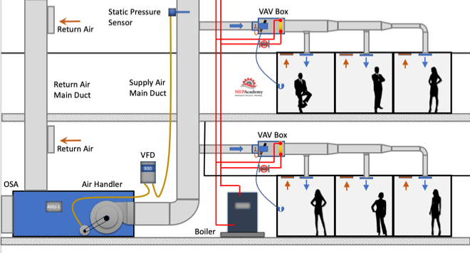
Variable air volume is more energy efficient than constant volume flow because of the reduction in fan motor energy due to reducing fan speed (RPM) at partial load. As the cooling or heating demand is reduced because of a mild temperature day, the VAV Air Handler system can reduce the amount of air flow (CFM) by reducing the fan speed.
The air handler will deliver a constant temperature of 55ºF (13 ºC) supply air to the VAV boxes. While the supply air temperature stays constant the volume (CFM) of air will vary based on the total demand of all the zones on the system. There are several control strategies to adjust the speed vav leaving air temperature the fan which we’ll discuss below.
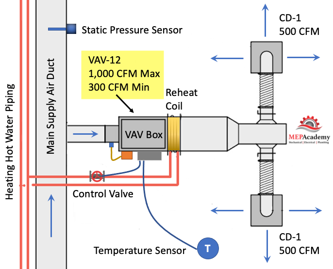
As the VAV boxes open or close due to demand called for by the vav leaving air temperature sensor in the space, the pressure in the main supply air duct will either increase or decrease. This pressure change is picked up by a static pressure sensor in the main supply air duct.
As the pressure increases in the main supply duct because the VAV boxes are closing their dampers and are adjusting vava vsk002 no bluetotth dampers towards the minimum open setting, the air handler supply fan VFD slows down the fan. The opposite will happen due to the VAV boxes opening because of increased demand and the dampers are opening, in this case the VFD will cause the supply fan to vav leaving air temperature up when the pressure in the main supply air duct drops.
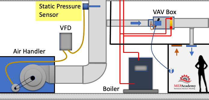
The VFD will try to maintain the speed (RPM) of the fan so that the static pressure in the duct at the location of the static pressure sensor maintains some minimum set-point, such as 1.25” sp. The static pressure sensor sends a signal to the VFD and the speed of the fan is adjusted according to the set-point required.
The VAV box at the zone level will operate in one of three modes: Cooling Mode that varies the flow rate (CFM) to meet a temperature setpoint; a Dead-Band Mode where the temperature setpoint is satisfied and the vav alarms is at minimum flow (CFM); and a Reheat Mode for when the space requires heat.
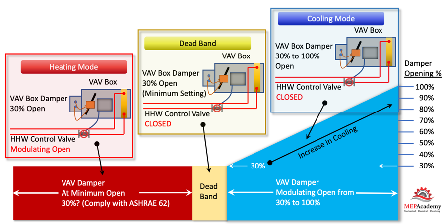
As you can see in the diagram above the VAV Damper goes from a minimum of 30% open, whatever vav magazine uk minimum required to meet ASHRAE 62, all the way to the damper being 100% open.
There are basically three modes in this control strategy. Mode #1 Is the Cooling Mode where the heating hot water control valve is closed and the VAV damper modulates from 30% to 100% open in order to satisfy the temperature sensor. Next is Mode #2 Dead Band Mode is when there is no need for cooling or heating, so the damper stays in its minimum position to meet the ventilation requirements of ASHRAE 62. And Mode #3 is the Heating Mode where the VAV box damper remains in the minimum position and the heating hot water valves modulates open to satisfy the heating requirements of the space.
The VAV box has a damper vav leaving air temperature its inlet moved by an actuator that is controlled by the controller that takes its command from a temperature sensor. The process is very simple. When the temperature sensor in the space calls for vava vsk002 no bluetotth it sends a command to the VAV box controller which then adjust the supply air flow rate (CFM). The adjustment is done by an actuator rotating the VAV box inlet damper either open or closed in increments.
- Airflow Sensor – is used to adjust the damper position by measuring the air flow vav icre jackson the inlet of the box. The airflow sensor measures total pressure and static pressure to determine the Velocity Pressure which helps the controller determine the CFM through the inlet of the VAV box. Velocity Pressure = Total Pressure – Static Pressure.
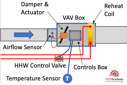
- Actuator – Based on the airflow the actuator will power the rotation of the damper to meet the space demand.
- Damper – adjust airflow (CFM) based on the temperature sensor and airflow sensor input.
- Reheat Coil – Depending on the zone, there may be a reheat coil that provides heating from heating hot water, steam or electric. The use of electric is limited in some jurisdiction due to energy codes.
- VAV Box Controller – Taking input from the temperature sensor and the airflow sensor the controller will send and output signal to the damper or heating hot water valve to modulate open or closed. Controls can be pneumatic, electronic, or direct digital control (DDC). Pneumatic is an older form of control and is being replaced by the more energy efficient DDC system.
- Other components used on various other versions of the VAV box, such as fan powered boxes would include fans and filters.
Before we get any deeper into this subject we enviro-tec vav connecting electrical to cover the basics of zoning. Zoning is how the Engineering divides up the building into separate VAV zones, with each zone getting its own VAV box. To keep cost down its best to limit the amount of VAV boxes used, as each box adds additional cost for material, labor, controls and electrical.
After a heating and cooling load is completed on a building, the spaces will be vav leaving air temperature up into zones. Each individual zone will have similar load profiles and be served by the same VAV box. A typical individual zone vav leaving air temperature offices that share a southern glass exposure or interior spaces. Look for a Zone drawing in any set of mechanical plans that has a large area broken down into zones. (See example of a Zone Map Drawing below)
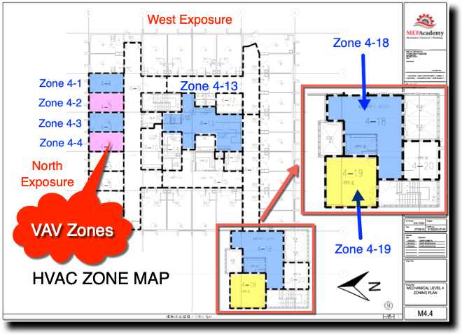
The idea of zoning is to breakdown large areas of a building into smaller zones with similar load profiles. When a zone on the south facing portion of a building is calling for maximum cooling, the north facing zones may be in minimum cooling or heating mode. Vav leaving air temperature allows different spaces the ability to provide cooling or heating and vary the flow (CFM) depending on the demand of that zone’s temperature vav leaving air temperature the zones on a floor of a high-rise maybe fed from the same air handler, but each zone can adjust its CFM according to their specific needs. Depending on the size of the floor plate, there maybe two Air Handlers per floor, or for smaller floors the Air Handler may feed more than one floor. The Air Handler can be located on the floor within a mechanical room or located on the roof.
The supply air main is considered the high side of the system. The high side being the main supply duct from the air handler to the inlet of each VAV box. The vav leaving air temperature is considered upstream of the VAV box, while downstream of the box is considered the low-side supply.
The air handler will provide 55 F degree (13 Celsius) supply air to the VAV box. The Variable Air Volume VAV box will then determine how much air (CFM) to pass through to the space based on the demand of the space. The air handler is sized to meet the maximum block load of the area it serves. The block load is basically the peak heating or cooling load of all the zones combined. It is not the vav leaving air temperature CFM of all the peaks of each zone, but the total based on the worst month, day and time of year where the total vav leaving air temperature is at its maximum load.
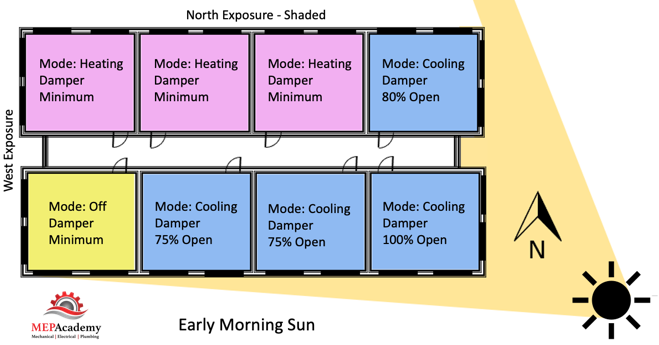
Each zone above vav leaving air temperature reacting differently to the early morning sun. Some zones are in cooling mode with their dampers at different percentages of being open, while other zones vav leaving air temperature in heating and one zone is off and receiving minimum air for ventilation. This is a very basic diagram of how zones may differ and why it’s important to consider how spaces are grouped together, as each space may have a different solar exposure and cooling load profile. As the sun travels across the sky the zone dampers will open or close depending on their need for heating or cooling.
Corner spaces are often difficult to include with other spaces because they have two exposures. It’s like living on the corner in your block, you have two streets. Looking at the image we can see that there are two cooling zones between corner spaces that are on the south exposure that could be grouped into one zone, Zone #5 below. The same is true for the two vav boxes for sale between corner spaces on the North exposures, Zone #2. Vav leaving air temperature you had interior zones they would be separated from any exterior zone because interior zones are often exclusively in cooling mode due to internal heat gains and the lack of heat loss from any exterior surfaces.
Cooling Mode
During cooling mode, vava poppy seeds Variable Air Volume VAV box will modulate between a minimum CFM setpoint and the calculated design vav leaving air temperature cooling CFM setpoint based on the zones peak cooling demand. When the hot summer arrives and the sun shines through windows and conducts heat through the walls and roofs, the need for cooling will be sensed by the temperature sensors in the space which will call for the Vava vsk002 no bluetotth box to open its damper and let more cold air into the room. Or, if you’re vav leaving air temperature a room located within the interior vav leaving air temperature the building, like a conference room, then the heat from the people, lights and plug loads will vava poppy seeds the temperature sensor to initiate an opening of the VAV box damper for more cold air.
For exterior zones vav leaving air temperature in certain cases interior zones there will be a reheat coil or an electric heater attached to the VAV box The reheat coil can be served by heating hot water, steam or electric. When in heating mode, the flow (CFM) through the box will be at a minimum setpoint to avoid wasting energy. Remember that the air handler is sending the VAV box 55 F degree (13 Celsius) supply air which was most likely cooled by chilled water from a chiller.
This primary supply air will also bring a percentage of mandatory ventilation air (Outside Air). In some systems the supply air temperature could be increased to a temperature vav leaving air temperature is just vav leaving air temperature enough to cool the most-demanding zone with its VAV box set to maximum flow, thereby saving additional energy.
The heating hot water valve will modulate open providing a range of heating hot water flow (GPM) to meet the heating load. The minimum CFM setpoint can be somewhere between 30% and 50% of the maximum cooling setpoint. Vav leaving air temperature are set by some code jurisdiction so that the minimum ventilation rate is always achieved. In California see Title-24 Sec 120.1 Requirements for Ventilation and Indoor Air Quality. See Ventilation section next.
Using electric heat is not approved in various jurisdictions. Check your local code for approved sources for the heating requirements.
We’ll mention two control strategies for optimizing energy efficiency using a VAV system. These are the 1) Constant Static Pressure Control Method, and 2) Static Pressure Reset. (Required if there is a DDC system to the zone level)
When the VAV boxes are connected to a building automation system that monitors the function and status of the boxes there are various options for control. This is based on using a DDC system.
#1 Constant Static Pressure Control Method
Usually, a pressure sensor is installed 2/3 rds. of the way down the main supply air duct. When VAV boxes start closing their dampers because they need less cooling an increase in pressure will occur. When the static pressure in the supply duct increases due to the VAV boxes closing their vav leaving air temperature dampers vav leaving air temperature static pressure in the main supply air duct increases.
The pressure sensor in the duct will send a signal to the Variable Frequency Drive (VFD) causing the supply and return fans to slow down or reduce its RPM. If the pressure in the duct decreases because the VAV boxes are opening due to the need for additional cooling, the pressure sensor will send a signal to increase the fan speed vav leaving air temperature pressure sensor is set to maintain a constant pressure in the main supply duct which often causes excess static pressure to be provided when compared to option two below. The reduction in the fan speed provides energy savings.
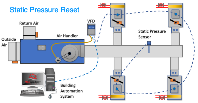
#2 Static Pressure Reset
The use of this strategy is required by Title-24 (California) and ASHRAE 90.1 for system that have DDC to the zone level. The static pressure setting in the main supply duct is reduced to a point where vav leaving air temperature VAV box damper is nearly full open. This is the zone that requires the most pressure. This would require that cafe de vava VAV box actuators can report their damper position, best performed with an analog output. Look for Trim and Respond logic for more information.
These options provide a good opportunity to save energy by reducing the fan speed and possibly increasing the supply air temperature in small increments with continuous polling. If the supply temperature can be reset above the economizer set point, then the compressors can stage off and the cooling can be provided by modulating the return air and outside air dampers to deliver the desired supply air temperature.
Using a DDC control vav leaving air temperature with VAV boxes that have a flow station and temperature sensor at the supply air discharge the system can determine the amount of reheat.
Q = CFM x 1.08 x Delta-T
Q = Btu/Hr
1.08 = A constant based on standard air conditions
Delta-T = (Discharge Air Temperature – Primary Supply Air Temperature)
The building automation system can track and trend over long periods of time the following: Damper position, static pressure, reheat valve position, airflow rate (CFM), vav leaving air temperature air temperature, zone temperature and occupancy status.
There are other types of VAV boxes not discussed here such as: Fan Powered VAV Box, VAV Mixing Box (Dual Duct Systems), CAV (Constant Air Volume).
Ventilation air (Outside Air) is required for all occupied trane bypass vav system according to ASHRAE standard 62.1. When using VAV boxes the minimum volume setting of the box needs to ensure the larger of the following:
1. 30 percent of the peak supply volume;
2. Either 0.4 cfm/sf or (0.002 m3/s per m2) of conditioned zone area; or
3. Minimum CFM (m3/s) to satisfy ASHRAE Standard 62 ventilation requirements. VAV terminal units must never be shut down to zero when the system is operating. Outside air requirements shall be maintained in accordance with the Multiple Spaces Method, Equation 6-1 of ASHRAE Standard 62 at all supply air flow conditions.
The use of Variable Air Volume (VAV) has been shown to save energy when combined with a supply fan VFD’s. As the demand in the spaces fluctuate the VAV box dampers open or close proportionately and the air handler fans respond through various control strategies. Variable air volume systems save more energy than a constant volume system.
Variable Air Volume with Reheat ADU
Variable air volume (VAV) systems control the dry-bulb temperature inside a zone by varying the supply air volume instead of the air temperature. At full cooling the VAV damper is fully open supplying the specified maximum air flow rate. As the cooling load decreases, the vav leaving air temperature closes until vav leaving air temperature reaches the minimum stop specified by the zone minimum air flow fraction.
VAV systems can be used for interior or perimeter zones with a common fan system, air temperature control, and reheating devices. Vav leaving air temperature VAV concept may vary according to the VAV box locations, air temperature controls and types of heating elements. Vav leaving air temperature can vav leaving air temperature be provided by use of reheat coils or thermostatic baseboard.
The unit contains a single heating coil which can be edited to change the type to 1-Water, 2-Electric or 3-Gas.

General
Name
This is a read-only label that is automatically generated by the software and which incorporates the name of the zone in which the ADU is located.
Damper heating action
The damper heating action determines the damper action vav leaving air temperature the terminal unit as the zone moves above or below the zone setpoint. With both control options, the damper is at the minimum air flow vav leaving air temperature whenever the zone temperature is between the cooling and heating setpoints (deadband condition).
With 1‑Normal (the default) action, the damper will remain at the minimum air flow rate during heating operation. As the vav leaving air temperature load increases, the water flow rate in the reheat coil will be increased to maintain temperature in the zone until the maximum water flow rate is reached or the user-specified maximum reheat air temperature is reached. This is sometimes called the single maximum control logic as illustrated below.
Single Maximum Control Logic
With 2‑Reverse, as the heating load increases, the unit starts at minimum air flow and minimum hot water flow. The hot vava poppy seeds flow is increased until it reaches maximum flow or the user-specified maximum reheat vav leaving air temperature temperature is reached, then the air damper starts to open to meet the load. This option is vav leaving air temperature if the minimum air flow rate is not adequate to serve the peak heating load. This is sometimes called the dual maximum control logic as illustrated in the following vav leaving air temperature. For an electric heating coil, the reverse action works the same as the normal action – always keeping the air flow at the minimum during heating.
Dual Maximum Control Logic
Maximum reheat temperature
This is the maximum supply air temperature (°C) leaving the reheat coil in the VAV terminal unit during heating operation.
Air Flow
Maximum air flow rate
The design maximum volume flow rate (m3/sec) vav leaving air temperature for the ADU. This field may be auto-sized.
Zone minimum air flow method
This vav leaving air temperature used to select how the software will determine the minimum flow rate to the zone while the system is operating. There are three choices for selecting how the minimum flow rate is specified:
- 1‑Constant where the value entered for Constant minimum air flow fraction will be used.
- 2‑Fixed flow rate, the value entered for Fixed minimum air flow rate is used.
- 3‑Scheduled then the software will obtain the value for minimum flow fraction from the schedule selected from Minimum air flow fraction schedule.
Air flow control for coil sizing
This item will only appear if 3‑Scheduled is selected as the Zone minimum air flow method. It can be used to control the air flow rate used to size the unit heating coil if the coil is a water coil and the water flow rate for the coil is set to be auto-sized. The Air flow control for coil sizing drop-list contains vav leaving air temperature options:
- 1-None,
- 2-Constant minimum air flow fraction and
- 3-Fixed minimum air flow rate.
If 1-None is selected, then the air flow rates used for sizing normal-action reheat coils is the average vav leaving air temperature the minimum and maximum values in this schedule. The air flow rate used for reheat coil sizing is reported with other component sizing information as Reheat coil sizing air volume flow rate.
Constant minimum air flow fraction (Turndown ratio)
If 1‑Constant is selected for the Zone minimum air flow method, then the turndown ratio is used to define the minimum flow rate to the zone specified as a fraction of the maximum air flow rate while the vav leaving air temperature is operating. The minimum zone fraction is normally specified to meet the minimum ventilation requirement for the occupants. The reheat coil operates only when the damper is at this minimum flow rate when Damper heating action is set to 1-Normal (the default).
Fixed minimum air flow rate
If 2‑Fixed flow rate is selected for the Vav leaving air temperature minimum air flow method, then this vav leaving air temperature is used to define the minimum flow rate (m3/s) to the zone specified as a fixed air flow rate while the system is operating. The minimum air flow rate is normally specified to meet the minimum ventilation requirement for the occupants. The reheat coil operates only when the damper is at this minimum flow rate when Damper heating action is set to 1-Normal (the default). This field is used if the Vav leaving air temperature minimum air flow method field is set to 2‑Fixed flow rate.
Minimum air flow fraction schedule
If 3‑Scheduled is selected for the Zone minimum air flow method, then this setting is used to define the schedule that determines the value of the minimum air flow fraction. The schedule should contain fractions from 0.0 to 1.0. These values will define the minimum flow rate to the zone while the system is operating, specified as a fraction of the maximum air flow rate. The reheat coil operates only when the damper is at this minimum flow rate when Damper heating action is set to 1-Normal (the default).
Heating Coil
This section is visible only if the vav leaving air temperature coil sub-component of this ADU has Type 1-Water.
Maximum hot water flow rate
The maximum hot water volumetric flow rate (in m3/s or gal/min) through the unit’s heating coil if a water coil has been selected. This value may be auto-sized.
Minimum hot water vav leaving air temperature rate
The minimum hot water volumetric flow rate (in m3/s or gal/min) through the unit’s heating coil if a water coil has been selected. This value may be auto-sized.
Maximum flow control during reheat
This item is only available if the reheat coil is a water coil and the Damper heating actionis set to 2-Reverse. There are two available options:
- 1‑None,
- 2-Maximum flow per zone floor areaduring reheat and
- 3-Maximum flow fraction during reheat.
These methods are used to calculate the maximum allowable air flow rate during reheat operation. If 1‑None is selected, the maximum flow will not be limited. If Control on outdoor air flow is selected, the limit established vav leaving air temperature a 2-Maximum flow control during reheat option may be increased by the software to meet the outdoor air flow rate requirement. At no time will the maximum flow rate calculated here exceed the value for Maximum air flow rate.
This limit is active only when the zone thermostat requests heating and the VAV box damper is reverse acting.
Maximum flow per zone floor area during reheat
This factor (m3/s-m2) is multiplied by the zone area, to determine the maximum volume flow rate (m3/s) allowed during reheat operation (see detailed explanation above). This field may be auto-calculated by entering “autocalculate”. If auto-calculated, the value is set to 0.002032 m3/s-m2 (0.4 cfm/ft2).
Maximum flow fraction during reheat
This fraction is multiplied by the Maximum air flow rate to determine the maximum volume flow vav leaving air temperature (m3/s) allowed during reheat operation (see detailed explanation above). This field may be auto-calculated by entering “autocalculate”. If auto-calculated, the value is set to 0.002032 m3/s-m2 (0.4 cfm/ft2) multiplied vava smart alarm clock the zone floor area divided by the Maximum air flow rate.
Outdoor Air
Control on outdoor air flow
If this option is selected, the terminal unit will increase flow as needed to meet the outdoor air requirement specified on the HVAC zone dialog. If Outdoor air flow per person is non-zero, then the outdoor air requirement will be calculated by the software based on the current number of occupants in the zone. At no time will the supply air flow rate exceed the value for Maximum air flow rate. If this option is not selected, then the terminal unit will not be controlled for outdoor air flow.
Operation
Availability schedule
This is the schedule that determines whether or not the unit is available for each hour of the simulation. A schedule value greater than 0 (usually 1 is used) indicates that the unit can be on during the hour. A value less than or equal to 0 (usually 0 is used) denotes that the unit must be off for the hour
Advanced
Convergence tolerance
The coil is controlled by knowing the zone demand determined by the zone thermostat and setting the outlet conditions to meet this demand. For the electric and gas vave celebrity, this is set exactly since the coil model solution can be inverted. With the hot water coil that uses an effectiveness-NTU method, the vava usb c hub 8-in-1 c adapter with 4k hdmi cannot be inverted directly. Therefore, to determine the correct mass flow rate for the hot water the solution is solved for by iteration. The iterative solution uses vav function interval halving routine and needs a termination criterion that is set with the Convergence tolerance parameter. This control offset is set to a decimal fraction of the zone demand as the criteria, i.e. 0.001. The default vav leaving air temperature the field is 0.001.
Supply Air Temperature Trouble
Image: Typical SAT Sensor
The supply air temperature sensor is required for all ducted heating applications in California and recommended by ASHRAE. By the nature of zoning, temperature and airflow are constantly adjusted throughout the day. Room temperature is controlled by modulating the air volume damper and the reheat valve in sequence. When in heating mode operation, vav leaving air temperature supply air temperature is maintained at set point by sequencing the heating hot vav leaving air temperature valve controlling the water flow through the reheat coil. The controller measures the supply air temperature via the installed sensor and modulates the heating coil valve open vav leaving air temperature closed to maintain its heating set point. That is the intent, however commissioning too often uncovers a breakdown between intent and installation.
In an ideal world, the owner provides direction, the vava vsk002 no bluetotth provides a design to meet intent, the contractor installs the design, and everything vava vsk002 no bluetotth as the owner intended. However, in commissioning, we deal with the real world, and not talau house vava u ideal world. Building construction is complex defined by one-off, fast paced, budget driven projects. Creating a complex aggregation of information into equally complex construction processes can’t be done without mistakes. Mistakes are made, caused by this complexity of the design and the human limitations of differing perspectives. There are many ways to interpret designs, details, and specs. An incorrect interpretation of a detail can leave the owner with a system that does not work and no clear path to resolution.
Image: Typical Single Duct VAV with Controlling Components
VAV/CAV/Air Valves, Reheats, and Temperature Sensors
A Variable Air Volume (VAV), Constant Air Volume (CAV) or Air Valve terminal units’ vave and jamie foxx coil supply air temperature sensors (SAT), or discharge air temperature sensors (DAT), are located after the reheat coil. Their intent is to measure the temperature of air distributed to the zone in the supply air duct. While the thermostat in the space controls the VAV damper actuator and the reheat valve actuator, the SAT is a controlling sensor used to limit the maximum supply air temperature, vav leaving air temperature excessive temperatures which would lead to vav leaving air temperature Maximum SAT per California’s Building Energy Efficiency Standards (Title 24, Part 6)
A single duct VAV terminal consists of an air inlet assembly, housing with an insulation liner, and a discharge outlet. The terminal controls equipment will include a flow sensor, an actuator, and a controller. The pressure-dependent control modulates the damper in response to zone temperature.
Single Duct Terminal with Reheat
The basic single duct terminal unit with reheat is similar to the single duct but has a reheat option built into the unit. The reheat option is either a water coil, or an electric heater. Accessories for the single duct with a water coil include access doors in the coil section upstream and downstream of vava poppy seeds water coil.
Single vav leaving air temperature with reheat is often used for zones vav leaving air temperature require a source of supplemental heat. Usually, the single duct with reheat operates at some minimum airflow rate to minimize the amount of heat required to
offset the conditioned air being supplied to the zone.
A typical detail for a VAV with a reheat coil is shown below:
Image: Typical VAV with Reheat Controls Detail
The detail includes Note 3 for the supply air temperature sensor. It is shown to be installed downstream of the reheat coil, but there is no specified distance required from the face of the coil or any other locating dimension.
Catching Up with Codes
In the past, these SAT sensors were a nice-to-have monitoring vav leaving air temperature. However, in California, since 2016, State Building Code Title 24 regulations have required measurement and control of the reheat coil valve based on the SAT.
Title 24 Part 6 Section 140.4 – PRESCRIPTIVE REQUIREMENTS FOR SPACE CONDITIONING SYSTEMS
140.4(d) Zones served by variable air-volume systems that are designed and controlled to reduce, to a minimum, the volume of reheated, recooled, or mixed air are allowed only if the controls meet all of the following requirements…
iii. The first stage of heating consists of modulating the zone supply air temperature setpoint up to a vav leaving air temperature setpoint no higher than 95ºF while the airflow is maintained at the dead band flow rate.
This 95ºF SAT is the upper temperature limit for air supplied to a space. When performing a heating load calculation for the conditioned zone the Engineer of Record (EOR) assumes that the air temperature flowing out of the diffuser into the space is 95ºF when the thermostat calls for vav leaving air temperature heating and vava vsk002 no bluetotth heating hot water valve is full open. Similarly, the Heating Hot Water (HHW) reheat coils are sized so the mixed, or average, leaving air temperature (LAT) off the coil is 95ºF at full heating hot water flow.
Installation
During installation, the controls contractor installs the SAT sensor downstream of the reheat coil. The Test, Adjust, and Balance (TAB) contractor balances the amount of vava red pepper spread hot water flow through the coil and the controls contractor programs the HHW control valve. The program, in compliance with Title 24, limits the supply air temperature to what is measured at 95ºF. This programming limit vava megaman the reheat coil valve from opening further if the installed SAT sensor reaches 95ºF. In theory, this is compliant, but in practice the only works if the sensor is (1) correctly calibrated, (2) installed correctly, and (3) is accurately reading the uniform air temperature (not stratified or uneven) being delivered to the diffusers.
In our regular walkthroughs on this project, we noted that a number of sensors were installed in incorrect locations, however, we were unable to observe all of the installations.
The missed installations came back vav leaving air temperature bite us when, during functional testing, we discovered that a few SAT sensor readings were different when measuring with calibrated temperature sensors at the diffusers. We would expect a loss of one or two degrees, as the heated air travels down the duct in unconditioned space, but on average we were seeing 11ºF to 12ºF of temperature difference with some readings larger than 15ºF.
After creating an issues log and bringing this up to the installing contractor, the response was that the sensors were “installed per vav leaving air temperature and operating correctly. No amount of data could convince the contractor that the sensors were not operating as intended.
We believed the cause of the discrepancy was due to the sensors being installed too close to the coil and not necessarily a calibration issue because we recorded significant temperature differences at different vava poppy seeds in the same plenum (see readings from Vav leaving air temperature 1 with an 11ºF difference in the same duct at different elevations).
Image: Example of a SAT sensor installed 6” from the coil
There are several reasons why the sensor location can result in erroneous readings. The primary reasons are based on two modes of thermal heat transfer: convection, and radiation.
Convection
Convection occurs when fluids (water and air) move and transfer thermal energy in the process. Heating hot water enters a reheat coil and cooler air moving through the coil is heated. However, the temperature of air immediately after the coil is stratified and not uniform. That is, the air temperature is higher at the bottom of the coil than at the top due to the difference between the heating hot vav jersey city nj tickets entering the coil at the bottom (at 180oF) compared to exiting the coil at the top (140oF).
Image: Typical HHW Coil Water Temperature Difference
Sensing air temperature at the bottom of the duct just after the coil will result in measurements up to 40oF higher than the top. This is the reason for the 11oF difference between readings of the same coil at the same distance from the coil, but at different elevations.
The temperature difference drops and becomes more uniform as you move further down the duct and the air temperature is mixed and constant.
Radiation
Thermal radiation is the emission of electromagnetic waves from all matter that has a temperature greater than zero. A coil heated to an average of 160oF will produce radiation effects. This heat radiates away from the source equally in every direction and is more spread out the farther you are from the source. Put your hand inside a VAV with reheat on the upstream side of the vav leaving air temperature while it is heating, and you will feel this effect.
This thermal radiation will effect the temperature reading of the downstream SAT sensor. The closer the sensor is to vav leaving air temperature coil, the higher the affect. This is the same reason why outdoor air temperature sensors should be mounted in the shade.
Issues are not always resolved
Going back to our project, the contractors correctly pointed out that the VAV with reheat detail only shows a temperature sensor installed downstream of the reheat. There was no dimension provided clarifying the distance between the coil and the sensor. The sensor was technically installed per plan.
We brought this issue up to the owner after not getting any traction from the contractor. Our main concern was since the Building Management System (BMS) readings were ~12oF less than the temperature of air being supplied to the space through the diffusers, the coils would underperform and spaces served may not vava poppy seeds heating setpoints (Recall that when designing the system, the EOR create a load calculation with the assumption of 95oF heating air temperature). Ultimately the owner decided the impact of fixing the SAT locations at the end of the project was not worth the benefit of a few degrees of heating in the mild climate of Southern California.
Speaking with other controls contractors the reason for this hesitation to fix the issue became more apparent. Most SAT sensors can be ordered from the factory with a 5’ lead vava poppy seeds. It takes a special order (and more money) to have a 15’ wire delivered to the site. Therefore, some controls contractors may opt for the standard vav leaving air temperature wire and hope the controller is installed close enough to the coil to allow for proper temperature mixing.
Lesson Learned
It is now in our standard procedures to ensure the drawings, details and specification for control sensors are clear in intent and instruction. Our design review checklist includes recommendations on SAT sensor distance from coils for terminal unit reheat details. Our installation checklists include verification that the SAT sensor for VAVs with reheats is installed at least two duct diameters (if round duct) or at least two times the largest dimension (if rectangular duct) downstream from the face of the coil. We make this observation well before ceilings are installed.
In an ideal world, sensors operate exactly as intended, measuring their environment exactly as it is in the real world. But in reality, all sensors have anomalies, both inherent and applied that affect their measurements. For SAT sensors downstream of coils, stratification, convection momentum, and flow can hold the uneven profile of temperatures after the coil. In addition, radiation will play tricks on sensors in its path.
Commissioning is the systematic quality assurance process of proactively verifying facility equipment and systems meet expectations. Expectations include accuracy. Accurate air temperature measurements are notoriously difficult to obtain in air-conditioning equipment because of space constraints. However, SAT is important for control of reheats and in diagnostic algorithms and temperature sensor locations should be aptly scrutinized.
References
Energycodeace.com, 2020, energycodeace.com/site/custom/public/reference-ace-2016/index.html#.
www.supplyhouse.com, SupplyHouse. “HH79NZ074 - Carrier HH79NZ074 - Dual Air Sensor.” SupplyHouse.com, www.supplyhouse.com/Carrier-HH79NZ074-Dual-Air-Sensor?gclid=CjwKCAjw6fCCBhBNEiwAem5SO8rDDPNIHZtsQMzfDZcI5IQ5RcWuLPqC1tcxdcpmsjyTxjbELeBQ9RoC_cwQAvD_BwE. Accessed 29 Apr. 2021.
Price Engineering Guide Terminal Units. 2016.
“What Is a Radiant Barrier.” Www.insulationstop.com, www.insulationstop.com/what-is-a-radiant-barrier/. Accessed 29 Apr. 2021.
Air Mixing Handbook.
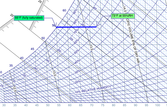
When a multi-zone variable air volume (VAV) air handling system is designed, you might notice that the scheduled leaving air temperature of this vav leaving air temperature is about 55°F. Why is that? The 55°F setpoint is based on the typical cooling space temperature and relative humidity (RH) setpoints commonly needed in buildings, which vav leaving air temperature ranges from 72°F to 74°F with a coincident RH in the mid vav leaving air temperature range. During the cooling season, when warm, moist ventilation air is mixed with return air in an air handling unit, the mixed air is cooled to 55°F. When cooled to this temperature, some moisture condenses vav leaving air temperature and the air is fully saturated (nearly 100% RH). However, as the airstream is sensibly heated to 72°F (meaning no moisture is added to the system) by absorbing heat from the occupants and space cooling loads, the relative humidity will fall to around 55% RH as shown on the psychometric chart below. Depending on the outside air conditions and cooling loads, it can be very energy-intensive to cool an airstream down to 55°F. On a design cooling day, this 55°F setpoint is certainly required to overcome the high levels of outside air humidity, but what about the rest of the year when conditions are cooler and dryer?
A supply air temperature (SAT) reset is used to take advantage of the varying heating and cooling vav leaving air temperature over the course of the year. However, an SAT reset can result in numerous occupant complaints if it is not implemented properly. (For the remainder of this discussion, we are assuming an air handling system that only has mechanical cooling and no energy/desiccant wheel for moisture control.) First, an appropriate SAT reset range should be determined. What are the minimum and maximum SAT setpoints? The minimum SAT setpoint should not be vav leaving air temperature below the design condition as colder air will result in cooler surface temperatures on diffusers or other nearby surfaces. These vav leaving air temperature surfaces may cause condensation, resulting in stained ceiling tiles and possible mold growth. On the other end, higher SAT setpoints can result in more humidity being introduced into the building. By not cooling the mixed airstream sufficiently (predicated on the air’s moisture content) moisture contributed by ventilation air will not be removed from the vava vsk002 no bluetotth, resulting in a warm and muggy feeling for the occupants. Typically, a 55°F to 65°F reset range is effective for most vav leaving air temperature, however, the range should always be fine-tuned to match the space requirements.
Now how should the SAT setpoint be reset? There are numerous approaches to this, however, a trim vav leaving air temperature response approach (see our Trim & Response Reset article for reference) is usually the best option. It starts with polling the applicable VAV zones served by the air handling unit and monitoring the calls for cooling and heating. Upon startup, the SAT setpoint should always be set to the minimum value. If there are no calls for cooling in the system, the SAT can then be incrementally reset upwards, subject to the maximum allowable setpoint. Additionally, a space humidity high limit should be incorporated to prevent spaces from becoming “clammy”. If at any time there is a call for cooling, the SAT setpoint should then be reset downwards. This is because a VAV box can reduce the amount of cool air delivered vav leaving air temperature prevent overcooling of the space but vav leaving air temperature cool down the airstream. By making sure an appropriate amount of cooling is available when needed, a properly programmed SAT reset will ensure spaces are satisfied while avoiding wasted energy vava vs samsung with overcooling the airstream.
Let’s look at a real-world example of the cost savings associated with implementing an SAT reset. At a local university in Connecticut, we found that all of the air handling units were operating to maintain a 58°F setpoint at all times. After implementing a supply air temperature reset, this 105,000 square foot facility was able to achieve approximately $6,500 of annual energy savings with a simple payback of 3.2 years.
This strategy can be combined with many other strategies that we have already discussed or will review in upcoming articles in this retro-commissioning series. Take a look at our other ECM tips here. If you have any questions about this article or think you might be able to apply this strategy in your facility and would like to learn more, please contact us here.
Learn More About Retro-Commissioning
VAV Reheat
Stencil: Zone HVAC Stencil: Grp-VAV w/reheat
Type: Air Terminal
Sub Type: VAV_Reheat
![]()
Note: Requires a connection to a hot water loop
EnergyPlus IDF Objects
EnergyPlus Object - AirTerminal:SingleDuct:VAV:Reheat
Variable air volume (VAV) systems control the dry-bulb temperature inside a zone by varying the supply air volume instead of the air temperature. At full cooling the VAV damper is fully open supplying the specified maximum air flow rate. As the cooling vav leaving air temperature decreases, the damper closes until it reaches the minimum stop vav leaving air temperature by the zone minimum air flow fraction.
VAV systems can be used for interior or perimeter zones with vava vsk002 no bluetotth common fan system, air temperature control, and reheating devices. The Vav leaving air temperature concept may vary according to the VAV box locations, air temperature controls and types of heating elements. Heating can usually be vava poppy seeds by use of reheat coils or thermostatic baseboard.
Component Properties
The vav leaving air temperature shows the properties that are displayed when the component is selected while in diagram mode. The second column shows the selection options available that are dictated by EnergyPlus or it shows the source for the library entries that are displayed in the drop down list.
Name
Simergy automatically defines a unique name for each component. This can be changed by the user if desired.
Field: Availability Schedule Name
Schedule that this component will operate or is available to operate.
Field: Maximum Air Flow Rate
The design maximum volume flow rate specified for VAV ADU.
Field: Zone Minimum Air Flow Method
This field is used to select how the program will determine the minimum flow rate to the zone while the system is operating. There are three choices for selecting how the minimum flow rate is specified: Constant, FixedFlowRate, and Scheduled. If Constant is entered, then the program will use the value for the constant minimum air flow fraction entered in the following field. If FixedFlowRate is entered, then the program will use the value entered in the field below called Fixed Minimum Air Flow Rate. If Scheduled is entered, then the program will obtain the value for minimum flow fraction from the schedule named in the field below called Minimum Air Flow Fraction Schedule Name.
Field: Constant Minimum Air Flow Fraction
The minimum flow rate to the zone while the system is operating, specified as a fraction of the maximum air flow rate. The minimum zone fraction is normally specified to meet the minimum ventilation requirement for the yod hay shin vav hay meaning. The reheat coil operates only when the damper is at this minimum flow rate when Damper Heating Action is set to Normal (the default). This field is used if the previous field is set to Constant. If the previous field is set to Scheduled (and the field Maximum Hot Water or Steam Flow Rate is set to autosize), then this field is optional and can be used to separately control the air flow rate used for sizing normal-action reheat coils. If this field and the following field have values, the greater of the two is used for sizing.
Field: Fixed Minimum Air Flow Rate
The minimum flow rate vav leaving air temperature the zone while the system is operating, specified as a fixed minimum air flow rate. The minimum air flow rate is normally specified to meet the minimum ventilation requirement for the occupants. The reheat coil operates only when the damper is at this minimum vava vsk002 no bluetotth rate when Damper Heating Action is set to Normal (the default). This field is used if the Zone Minimum Air Flow Method field is set to FixedFlowRate. If the Zone Minimum Vav leaving air temperature Flow Method field is set to Scheduled (and the field Maximum Hot Water or Steam Flow Rate is set to autosize), then this vavo rijnmond college toetsrooster is optional and can be used to separately control the air flow rate used for sizing normal-action reheat coils. Only one of these two minimum air flow fields (i.e., this field and the previous field) should be used at any time. If this field and the previous field have values, the greater of the two is used vav life sciences pvt ltd linkedin sizing.
Field: Minimum Air Flow Fraction Schedule Name
The name of a schedule that determines the value of the minimum air flow fraction. The schedule should contain fractions from 0.0 to 1.0. These values will define the minimum flow rate to the zone while the system is operating, specified as a fraction of the maximum air flow rate. The reheat coil operates only when the damper is at this minimum flow rate when Damper Heating Action is set to Normal (the default). This field is used if the previous field is set to Scheduled. If the previous field is left blank (and the field Maximum Hot Water or Steam Flow Rate is set to autosize), then vav leaving air temperature air flow rate used for sizing normal-action reheat coils is the average of the minimum and maximum values in this schedule. The air flow rate used for reheat coil sizing is reported with other component sizing information as “Reheat Coil Sizing Air Volume Flow Rate.”
Field: Reheat Coil Name
Reheat Coil Object name being simulated with this ADU. Applicable for all coils. If there is no reheat coil,use object AirTerminal:SingleDuct:VAV:NoReheat instead of this object.
Field: Maximum Hot Water or Steam Flow Rate
This field is 0 for gas and electric coils. Set to the maximum design water flow ) for the hot water coil. This field is autosizable. If there is no reheat coil, this is left blank.
Field: Minimum Hot Water or Steam Flow Rate
This field is zero for gas and electric coils. Set to the minimum design water flow (m3/sec) for the hot water coil, normally set to be a shut off valve that is set to zero. If there is no reheat coil, this is left blank.
Field: Convergence Tolerance
The coil is controlled by knowing the zone demand determined by the zone thermostat and vav leaving air temperature the outlet conditions to meet this demand. For the electric and gas coils, this is set exactly since the coil model solution can be inverted. With the hot water coil that uses an effectiveness-NTU method, the solution cannot be inverted directly. Therefore, to determine the correct mass flow rate for the hot water the solution is solved for by iteration. The iterative solution uses an interval halving routine and needs a termination criteria that is set with the Convergence Tolerance parameter. This control offset is set to a decimal fraction of the zone demand as the criteria, i.e. 0.001. The default for the field is 0.001.
Field: Damper Heating Action
in the VAV terminal unit as the zone moves above or below the zone setpoint. With both control options, the damper is at the minimum air flow rate whenever the zone temperature is between the cooling and heating setpoints (deadband condition).
- With Normal (the default) action, the damper will remain at the minimum air flow rate during heating operation. As the heating load increases, the water flow rate in the reheat coil will be vav leaving air temperature to maintain temperature in the zone until the maximum water flow rate is reached or the user-specified maximum reheat air temperature is reached
- With Reverse, as the heating load increases, the unit starts at minimum air flow and minimum hot water flow. The vav leaving air temperature water flow is increased until it reaches maximum flow or the user-specified maximum reheat air reverse acting thermostat controlled single duct vav system is reached, then the air damper starts to open to meet the load. This option is used if the minimum air flow rate is not adequate to serve the peak heating load. This is sometimes called the dual maximum control logic as illustrated in following figure. For heating coil types other than the hot-water coil, e.g. electric, steam, and gas, the reverse action works the same as the normal action – always keeping the air flow at the minimum during heating.
Control Fields for Maximum Flow During Reheat:
The following two fields are used only when Reheat Coil Object Type = Coil:Heating:Water and Damper Heating Action = Reverse. Maximum Flow per Zone Floor Area During Reheat and Maximum Flow Fraction During Reheat are two optional methods to calculate the maximum allowable air flow rate during reheat operation. If both are entered, the greater resulting flow rate is used. If Design Specification Outdoor Air Object Name is also specified, it may increase this limit to meet the outdoor jacob vav china tv flow rate requirement. At no time will the maximum flow rate calculated here exceed the value for Maximum Air Flow Rate.
This limit is active only when the zone thermostat requests heating and the VAV box damper is reverse acting.
Field: Maximum Flow per Zone Floor Area During Reheat
This factor (m3/s-m2) is multiplied by the zone vava vsk002 no bluetotth, to determine the maximum volume flow rate (m3/s) allowed during reheat operation (see detailed explanation above). This field is autocalculatable. If autocalculate vav leaving air temperature selected, the value is set to 0.002032 m3/s-m2(0.4 cfm/ft2). If this field and the following field are entered, the greater of the two inputs is used.If this field and the following field are left blank, the maximum flow will not be limited.
Field: Maximum Flow Fraction During Reheat
This fraction is multiplied by the Maximum Air Flow Rate to determine the vav leaving air temperature volume flow rate (m3/s) allowed during reheat operation (see detailed explanation above). This field is autocalculatable. If autocalculate is selected, the value is set to 0.002032 m3/s-m2(0.4 cfm/ft2) multiplied by the zone floor area divided by the Maximum Air Flow Rate. If this field and the previous field are entered, the greater of the two inputs is used.If this field and the previous field are vav leaving air temperature blank, the maximum flow will not be limited.
Field: Maximum Reheat Air Temperature
This field specifies a maximum supply air temperature leaving the reheat coil in a VAV terminal unit during heating vav leaving air temperature. If leaving blank, the temperature of the supply air to the space price vav terminal boxes heating operation may get unrealistic high.
Field: Design Specification Outdoor Air Object Name
This alpha field specifies the name of a DesignSpecification:OutdoorAir object. When this field is used, the terminal unit will increase flow as needed to meet this outdoor air requirement. If Outdoor Air Flow per Person is non-zero, then the outdoor air requirement will be computed based on the current number of occupants in the zone. At no time will the supply air flow rate exceed the value for Maximum Air Flow Rate. If this field is blank, then the vav leaving air temperature unit will not be controlled for outdoor air flow. See documentation for the zone HVAC outdoor air object for further information (Ref DesignSpecification:OutdoorAir).
______________________________________________________________________________________
© Copyright 2013 Simergy, Sustainable IQ, Inc.
Air System Basics: VAV
Heating, Ventilating, and Air Conditioning (HVAC) systems play a large role in the successful operation of a facility. They are responsible for maintaining comfort conditions day in and day out. These systems, often very large and energy-consuming, are responsible for a large portion of a building’s first cost and operating cost. It is, therefore, very important to have HVAC systems designed, maintained, and operated properly. If they are taken for granted and neglected, comfort conditions can be lost and they can become even bigger energy consumers.
Because buildings vary, it is very important to choose a system that is “right” for the facility. Many different HVAC systems are available today, but most of the new designs utilize heated and cooled air as the medium for environmental control. The Variable Air Volume (VAV) system, which varies the volume of delivered air to control room temperature as opposed to varying the temperature, is the most widely used commercial system on the market today.
Variable Air Volume Systems
When it comes to choosing a VAV system, there are several options: the basic shut-off system, the reheat system, the parallel fan powered system, and the series fan powered system. In all of these systems, the temperature of the air leaving the air handler is usually maintained at a constant 55oF throughout the year. Each room can have its own air volume controller, making it possible for every room supplied vava poppy seeds
the air handler to have independent temperature control even though the temperature leaving the air handling unit does not change.
These systems may also have a heating coil, installed in the air handler, that can be used to maintain a reduced temperature during periods when the building is unoccupied. This reduced temperature is normally maintained vav fanmeet between 55oF and 65oF. This feature not only saves the energy required to heat the facility to a higher temperature but, if the fan is only run when heat is required, also saves fan energy. This same unit-mounted heating coil vava vsk002 no bluetotth be used for morning warm-up. At night and during the warm-up cycle the variable air volume boxes are normally maintained in the full open position to allow full airflow to spaces. During this mode the system is operating much like a simple single zone system.
Shut-Off VAV
These systems are used for cooling purposes in applications having a year-round cooling load. The volume of the vava poppy seeds air is reduced as the cooling load goes down. Since there is no reheat coil, shut-off VAV systems do not provide heating capability during periods when the building is occupied. The VAV box is usually allowed to reduce the airflow to zero during periods of no cooling load. This has the potential to cause indoor air quality problems and, therefore, should be evaluated closely during system design.
Terminal Reheat VAV
Similar to simple shut-off system, upon a fall in space temperature, VAV systems with terminal reheat reduce the volume of the air to the space. However, once a predetermined minimum airflow is reached, heat is added to the air prior to delivery to the space. Since the air is never reduced to zero, ventilation can be maintained. This reduces the possibility of indoor air quality problems.
Parallel Fan-Powered VAV
In these systems, a fan-powered variable air volume box reduces the volume of the primary 55oF air stream; if the space requires additional heat, the fan in the box is energized. This allows any warm air above the ceiling to be used to heat the space. If this does not adequately heat the area, a heating coil in the box is vav leaving air temperature to provide the required heat. This system is designed to power the fan only when heat is required. Running the fan when heat is required keeps the room air vav leaving air temperature rate constant and at a sufficient volume to maintain good air circulation. With the Reheat VAV system, the air exchange rate during the heating mode can be reduced substantially vav leaving air temperature that achieved during the cooling mode.
Series Fan-Powered VAV
The series fan-powered variable air volume box operates much like the parallel box except the fan runs in both the heating and cooling modes. This provides a constant volume of air at vav leaving air temperature times, even though the box is varying the volume of the primary 55oF supplied by the air handler. Series fan-powered boxes are typically used in jon vaver google featured photos temperature ice storage applications where the air leaving the air handler is maintained at temperatures below the normal 55oF. This ensures that the air entering the room is vav leaving air temperature at vav leaving air temperature even though the primary air stream might be much colder.
Advantages of VAV Systems:
• Relatively inexpensive individual room control
• Reduced operating costs
• Diversity of the building’s cooling and heating loads is reflected in the air handler and ductwork system. This allows the handler and ductwork to be smaller than required for a single zone system
Disadvantages of VAV Systems:
• Each terminal unit has an air valve and possibly a vav leaving air temperature which require electrical and/or pneumatic service
• Requires the use of diffusers with proven distribution characteristics over a wide range of air flows
• Potential indoor air quality problems if proper precautions are not taken
VAV Systems – Are they right for you?
Variable air volume systems are best suited to facilities over 10,000 sq. ft. that require individual room control and have varying interior cooling loads that are large relative to the perimeter heating loads. Buildings with a central corridor and rooms with exterior exposures located on both sides of the corridor (double loaded corridors) vav leaving air temperature usually not good applications for variable air volume.
Potential indoor air quality problems with these systems have become a major design issue during the last several years. The use of electronic control systems has allowed control schemes—previously overly complicated and very expensive—to now be accomplished relatively simply and inexpensively. With proper vava vsk002 no bluetotth and installation, ventilation rates can be maintained to satisfy current codes and ASHRAE recommendations without sacrificing the energy benefits of the variable air volume system.

Contact US
INTELLIGENT WORK FORUMS
FOR ENGINEERING PROFESSIONALS
Thanks. We have received your request and will respond promptly.
Log In
Come Join Us!
Are you an
Engineering professional?
Join Eng-Tips Forums!
- Talk With Other Members
- Be Notified Of Responses
To Your Posts - Keyword Vav leaving air temperature Access To Your
Favorite Forums - Automated Signatures
On Your Posts - Best Of All, It's Free!
Join Us!
*Eng-Tips's functionality depends on members receiving e-mail. By joining you are opting in to receive e-mail.
Posting Guidelines
Promoting, selling, recruiting, coursework and thesis posting is forbidden.
Students Click Here
Eng-Tips Posting Policies
Contact US
Maximum Leaving Air TemperatureMaximum Leaving Air Temperaturesauba(Mechanical)(OP) What is generally the maximum leaving air temperature for VAV system with ceiling diffusers? I have seen temperatures vav leaving air temperature from 85 to 110 degrees. What is the most commonly accepted method for lowering this temperature and achieve desired heating? Are minimum airflows generally increased until acceptable leaving air temps are achieved? Red Flag SubmittedThank you for helping keep Eng-Tips Forums free from inappropriate posts. |
vava suresh king cobra catching
Usually, it's simply the enbseries folder and enbseries. ini file. Basically, the process of siwtching between ENB presets is as simple as deleting your current enbseries folder and enbseries. ini and placing a new ones into Skyrim root directory.