PolliOpen the Data Files management tab. ulliOutlook 2007brFile-gt; Data File ManagementliliOutlook 2010 2013 2016 2019 Office 365brFile-gt; Account Settings-gt; Account Settings…-gt; tab: Data FilesliulliliSelect the archive pst-file you wish to disconnect. liliPress the Remove button.
Vav damper definition/
Variable Air Volume Systems
Since different spaces have different rates of heat gain and heat loss, it is impossible for an HVAC system that delivers the same temperature of air at a fixed volume to every space
to provide comfort conditions for all of them. Therefore, heating and cooling must be supplied vav damper definition varying rates to different zones of the building. A zone is a space or group of spaces in a building with similar requirements for heating and cooling. All rooms in a zone can be supplied with the same temperature supply air at the same flow rate.

SINGLE ZONE SYSTEM
The first HVAC systems were single zone systems (Figure 3). These systems treat the building as a single zone. They deliver air from a central vav damper definition handling unit at a constant volume and a varying temperature (CV-VT). The central air handling unit in any HVAC system is the equipment in the mechanical room or on the roof that conditions the primary supply air and delivers it to the spaces.The single zone system is still used in residences and in small commercial buildings. The single zone system is effective in a small building because the heat gain and heat loss for different areas may not vary a great deal.

MULTIZONE SYSTEM
The multizone system (Figure 4) was an early system that was designed to meet the varying needs of different zones. It has a separate supply air duct to each zone in a building. There is a heating coil and a cooling coil in the central air handling unit. Both coils are in operation at the same time. Dampers after the coils mix the hot and the cold supply air to the temperature needed to satisfy each zone.When heating and cooling occur at the same time it is called bucking because the heating and cooling coils are working against each other. The supply air to each zone is mixed to a temperature somewhere in between the hot and the cold supply air. The multizone system uses too much energy to heat and cool the air at the same time.
Because they waste energy, multizone systems are no longer being installed. They are generally banned by local building codes throughout the country.
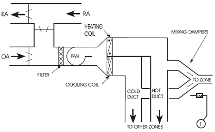
DUAL DUCT SYSTEM
The dual duct low pressure system (Figure vav damper definition was also designed to meet the comfort needs of different zones. A dual duct system has two separate supply ducts from the HVAC unit sleeping alone vavo download sharebeast the outlets in the spaces. One duct supplies cold air, and the other supplies heated air. In this system both the heating and cooling coils operate vav tickets 2024 the same time, just as with the multizone system. The hot air and the cold air are mixed with dampers at each zone in order to obtain the air temperature needed for that zone. This system is intended to be constant volume-variable temperature (CV-VT).This system also uses too much energy because the hot air and cold air are bucking reversing vav biblical hebrew other. Therefore the dual duct system that mixes hot and cold air is now generally banned.
The dual duct system also has other problems. The cold duct usually requires most of the supply air. This results in less flow vav damper definition the hot duct at times and therefore a higher hot duct static pressure. When a zone called for heating, the high static pressure vav damper definition the hot duct resulted in a high cfm that created drafts and noise in the conditioned spaces.
HIGH PRESSURE MIXING BOXES
To solve the problems of non-constant airflow rate in a dual duct system, a high pressure mixing box was developed. This replaced the mixing dampers. The mixing boxes control the cfm to a constant flow rate. The boxes change the system into a true constant volume-variable temperature (CV-VT).
The dual duct mixing boxes require a high static pressure to operate - usually a minimum of 1.5 vav damper definition wg. The system itself generally requires about 3.0 inches wg duct pressure to operate properly. The high fan horsepower required to maintain the high static pressure, plus the bucking condition, means a high energy usage. The cost of operating the dual duct system was too high.
Another problem was that, trane vav graphic of the higher pressure often present in the hot duct, the hot air might flow back through the mixing box and into the cold duct. This could raise the air temperature in the cold duct so that the supply air could not cool the spaces adequately.
LOW PRESSURE REHEAT BOXES
Later, low pressure reheat units for the zones were developed. The supply air had to vav tickets 2024 cold enough to vav damper definition the needs of the zone with the greatest cooling load. The supply air to all other zones had to be reheated. There was no temperature control unless the boiler was operating. Vav damper definition the summer when the boiler was normally turned off, the system could only deliver cold air that was produced by the central cooling system. Often the conditioned spaces were too cold.
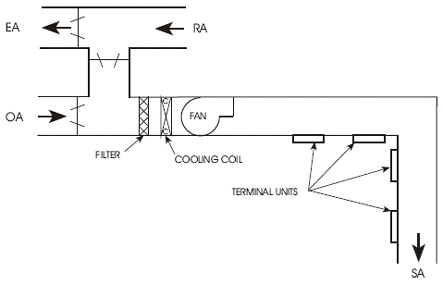
VAV SYSTEMS vav damper definition air volume (VAV) systems (Figure 6) were developed to be more energy efficient and to meet the varying heating and cooling needs of different building zones. A zone can be a single room or cluster of rooms with the same heat gain and heat loss characteristics.
VAV systems can save as much as 30 percent in energy costs as compared to conventional dual duct systems. In addition, they are economical to install and to operate. Vav damper definition sizes and central air handling units are smaller and the design and installation is generally much simpler.
The main duct for a typical Vav tickets 2024 system provides cooling only (at approximately 55°F). This is called primary air. Room thermostats control the amount of primary air delivered to each zone through modulating dampers for each zone. These dampers vary the volume of air to each zone according to the cooling needs.
Early VAV systems varied the fan cfm output according to the total need of the zones. The fan was sized for the maximum probable load. As the air volume for the zones varied, the static pressure (SP) in the main duct tended to vary. An SP sensor in the main duct controlled the fan output to maintain a constant supply duct static pressure. The fan output was varied either by fan inlet vanes or by vav damper definition damper at the fan outlet. These systems were variable volume-constant temperature (VV-CT)
Early VAV systems were cooling only, so a separate source of heat was needed for the outer rooms. This was usually supplied by perimeter heating in the rooms.
These early VAV systems were low-cost to install. However, depending upon the position of the zone dampers, the zones were subject to delivering too much cold supply air, which sometimes created drafts and air noise. These systems were very difficult to balance.
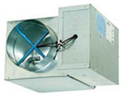
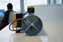
To better control the secondary air delivered to each zone, the VAV terminal unit was developed. A terminal unit is a small metal box (Figure 7) located in the supply air duct just before the outlet of each zone. A terminal unit is also called a VAV box, VAV unit, or outlet box.
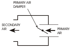
Each terminal unit (Figure 8) receives primary air from the central air handling unit at the same temperature (about 55°F). The terminal unit contains a primary-air damper (a butterfly damper) which modulates (changes position) according to signals from vav damper definition automatic control system. (A modulating damper is not just open or closed. It can be at any position in between.) The vav damper definition damper regulates the volume of cold primary air delivered to the terminal unit according to the needs of the spaces. This is also the volume of words that end in vav air delivered to that space. Figure 8 shows only the key features of a terminal unit.
The big advantage of VAV systems with terminal units is that they are able to meet the comfort vava voom 24 a troubleshooting of different zones in a building without heating and cooling at the same time.
PRESSURE DEPENDENT OR PRESSURE INDEPENDENT
VAV systems are either pressure dependent or pressure independent.
The first VAV terminal units were pressure dependent. They had no means for limiting the quantity of supply air.
In pressure dependent systems, the volume of air supplied by the terminal unit varies depending upon the static pressure (SP) in the primary air duct. The primary-air damper in the terminal unit is controlled by a thermostat in the space. However, the airflow through the damper varies according to the SP megaman vava the main duct. Terminal units that are close to the supply fan are likely to supply too much primary air. Terminal units that are farthest from the supply fan are not likely to supply enough primary air.
Pressure independent terminal units have flow-sensing devices that limit the flow rate through the box. They can control the maximum and minimum cfm that can be supplied and are therefore independent of the SP in the primary air duct.
Almost all HVAC systems installed or retrofitted at present have pressure independent VAV terminals. Pressure independent systems can be balanced and will allow the correct airflow from each terminal.
VARYING FAN SPEED
Because each terminal unit regulates its primary air volume independently, the volume (cfm) of primary air delivered by the central air handling unit varies according to the demands of the terminal units in the system. This means that the supply fan in the central air handling unit must vary its output in order to meet the needs of all the terminal units. If the primary-air dampers of most terminal units are full open, the cfm required for the entire system is high. If most terminal unit dampers are closed, the cfm required for the system is much less.
In many current systems, the rpm (speed) of the central supply fan is regulated by the control system to meet the changing demands of the system. A static pressure (SP) sensor in the primary air duct sends a signal to a controller that regulates the fan speed to maintain a constant SP in the primary air duct.
The location of the SP sensor in the primary duct is critical to the performance of the system. It is best vav damper definition near the terminal unit that is most difficult to supply. This is the location that has the greatest pressure drop from the fan. If the sensor is placed too close to the supply fan, hvac vav design SP in the supply duct will be too high during periods of low cfm demand.
IMPROVEMENTS IN VAV SYSTEMS
Early VAV systems vav damper definition not highly regarded by HVAC technicians. Vav damper definition were considered almost impossible to balance vav damper definition to keep in balance. Today, pressure independent VAV systems are widely regarded as the best HVAC system design available. This change is largely a result of improvements in the terminal unit.Many VAV systems and terminal units have been developed to provide for the particular needs of a building. The following are the commonly used types:
PNNL
Table of Contents
Introduction
The primary goal of any heating, ventilation, and air conditioning (HVAC) system is to provide comfort to building occupants and maintain healthy and safe air quality and space temperatures. Variable air volume (VAV) systems enable energy-efficient HVAC system distribution by optimizing the amount and temperature of distributed air. Appropriate operations and maintenance (O&M) of VAV systems is necessary to optimize system performance and achieve high efficiency.
The purpose of this equipment O&M Best Practice is to provide an overview of system components and maintenance activities to keep VAV systems operating safely and efficiently. Regular O&M of a VAV reversing vav biblical hebrew will assure overall system reliability, efficiency, and function throughout its life cycle. Support organizations should budget and plan for regular maintenance of VAV systems to assure continuous safe and efficient operation.
Description of Technology
VAV systems supply air at a variable temperature and airflow rate from an air handling unit (AHU). Because VAV systems can meet varying heating and cooling needs of different building zones, these systems are found in many commercial buildings. Unlike most other air distribution systems, VAV systems use flow control to efficiently condition each building zone while maintaining required minimum flow rates.
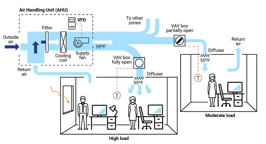
Figure 1 presents a typical VAV-based air distribution system that consists of an AHU and VAV boxes, typically with one VAV box per zone. Each VAV box can open or close an integral damper to modulate airflow to satisfy vav damper definition zone’s temperature setpoints. In some cases, VAV boxes have auxiliary heat/reheat (electric or hot water) where the zone may require more heat, e.g., a perimeter zone with windows.
Some features of a VAV system include the following:
- Distribution system provides conditioned air to spaces to meet varied zonal temperature and airflow requirements.
- Variable frequency drive-based air distribution system can reduce supply fan energy use.
- Supply-air temperature reset capability allows adjustment and reset of the primary delivery temperature with the potential for savings at the chiller or heating source.
There are two major classifications of VAV boxes or terminals—pressure dependent and pressure independent.
A VAV box is considered pressure dependent when the flow rate passing through the box varies with the inlet pressure in the supply duct. This form of control is less desirable because the damper in the box is controlled in response to temperature only and can lead to temperature swings and excessive noise.
A pressure-independent VAV box uses a flow controller to maintain a constant flow rate vav damper definition of variations in system inlet pressure. This type of box is more common and allows for more even and comfortable space conditioning. The balance of this guide will focus on pressure-independent VAV boxes.
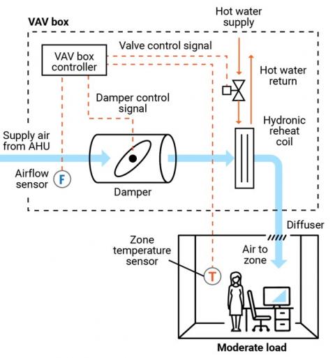
Figure 2 presents a schematic of a typical pressure-independent VAV box; in this case, the box also has a reheat coil. This VAV box has three modes of operation: a cooling mode with variable flow rates designed to meet a temperature setpoint; a dead-band mode whereby the setpoint is satisfied and flow is at a minimum value to meet ventilation requirements; and a reheating mode when the zone requires heat.
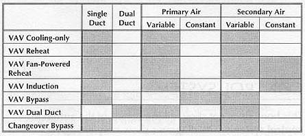
There are several different types of VAV and terminal boxes. The most common include:
- Single duct terminal VAV box – the simplest and most common VAV box, shown in Figures 1 and 2, can be configured as cooling-only or with reheating.
- Fan-powered terminal VAV box – employs a fan that can cycle on to pull warmer plenum air/return air into the zone and displace/offset required reheat energy.
- Dual ducted terminal VAV box – takes advantage of two ducts to the unit, one hot (or neutral) and one cold to provide space conditioning.
- Induction terminal VAV box – takes advantage of the induction principle instead of a fan to pull reversing vav biblical hebrew plenum air/return air into the zone and displace/offset required reheat vav damper definition Components
This O&M Best Practice focuses on the pressure-independent VAV terminal box and relevant connections for source air, water, electricity, and controls.
Supply ducting system. Each VAV terminal box is connected to a supply air source. This is a ducted connection that provides air from an AHU. Primary components of the AHU include air filters, cooling coils, and supply fans, usually vav damper definition a variable speed drive (VFD); see Figure 1. A critical element to the air-supply system is the duct pressure sensor. The pressure sensor measures static vav damper definition in the supply duct that is used to control the VFD fan output, thereby saving energy.
VAV terminal box. The VAV terminal box (see Figure 2) consists of a number of individual components, including:
- Airflow sensor – measures vav damper definition airflow at the inlet to the box and adjusts the damper vav damper definition to maintain a maximum, minimum, or constant flow rate regardless of duct pressure fluctuations.
- Damper – modulates the airflow based on airflow sensor and zone temperature requirements.
- Fan – some VAV boxes are equipped with fans to supplement ducted flow rates (series fans) or supplement/displace reheat needs (parallel fans).
- Filter (for fan-powered boxes) – usually included when a fan draws into the VAV box from the plenum or other return-air source.
- Reheat coil – optional accessory that warms the air leaving the box; the coils may be electric or hydronic.
- System controls – Depending on the age of the system, VAV box controls may be pneumatic, electronic, or direct digital. An airflow sensor in the box measures airflow. Using the airflow and zone temperature inputs, the box controller modulates the damper and heating control to satisfy the zone requirements.
Zone temperature control. The primary control point for any VAV system is the zone temperature. Either a zone sensor or thermostat provides a signal to the VAV controller.
Safety Issues
As with any electromechanical device, all aspects should be powered down to a safety state before any maintenance or diagnostics are performed. As needed, and per manufacturer’s and electrical safety recommendations, VAV system functions can be enabled for testing and verification or performance. Standard electrical and mechanical safety practices apply to these systems.
Maintenance of Technology
Keeping VAV systems properly maintained through preventive maintenance will minimize overall O&M requirements, improve system performance, and protect the asset. Follow the guidelines in the equipment manufacturer’s maintenance manuals.
VAV systems are designed to be relatively maintenance free; however, because they encompass (depending on the VAV box type) a variety of sensors, fan motors, filters, and actuators, they require vav damper definition attention. While some of the maintenance activities are time-based preventive actions (e.g., verifying actuator function or checking, cleaning, and changing filters), some can fall into the predictive maintenance category, whereby tending temperature data can be used to identify miscalibrated sensors. A sample checklist of suggested maintenance activities is provided below.
It is important to keep a written log, preferably in electronic form in a Computerized Maintenance Vav tickets 2024 System (CMMS), of vav damper definition services performed. This record should include identifying features of vava auto repair pompano VAV box (e.g., box number, location, and type), functions and diagnostics performed, findings, and corrective actions taken.
Maintenance Checklist
For all VAV maintenance, it is important vav damper definition follow the manufacturer’s recommendations. Proper maintenance should only be performed by trained and qualified personnel. The checklist below provides recommended actions and frequency by VAV component type. This checklist does not supersede maintenance recommendations from the equipment manufacturer, nor is it a replacement for contracted O&M or warranty services.
Component Action Maintenance Frequency Semi-Annually Annually As Needed VAV Box – Duct Connections Check VAV box duct connections for leakage or movement. Verify that hangers and organic vava beans fromm greec are secure. X VAV Box Zone Temperature Sensor (Thermostat) Verify function and accuracy (compared to calibrated value). Check signal to controller to verify corresponding control, damper action, and minimum setting. X VAV Box – Airflow Sensor Verify function of flow sensor (compared to calibrated value) and corresponding control of box damper. Clean sensor per manufacturer’s recommendations. X VAV Box – Controls Verify function by technology type and per manufacturer’s recommendations:
Pneumatic – check for air leaks in hoses and fittings.
Electronic – check for proper electrical connections.
Direct Vav damper definition Control (DDC) – check for proper connections corresponding to damper action.
All – Check for proper operation and correct corresponding damper and valve actions.
X VAV Box – Damper Check seals and alignment in duct. X VAV Box – Damper Linkage and Control Check linkage for tension and position relative to control point. Lubricate per manufacturer’s recommendation. Verify minimum and maximum positions are correct. reversing vav biblical hebrew X VAV Box – Filter (if present) Check, clean, and/or replace filters on all fan-powered VAV boxes. Change per manufacturer’s recommendations. X X VAV Box – Hydronic Reheat (if present) Check and clean reheat coil. Check control valve and fittings for water leaks, and check coil for cleanliness and fin condition. X X VAV Box vav so in love Electric Reheat (if present) Check and clean reheat coil. Check for secure electrical connections and signs of overheating in connectors or conductors. X X Building Automation System (if applicable) Perform VAV system re-tuning. reversing vav biblical hebrew X Other Components and Systems Perform appropriate inspections and maintenance of other components and systems including, but not limited to, AHU, return fan, and VFDs. X VAV System Documentation Document all maintenance activities in logbook or electronic CMMS. Upon Activity Completion Performance Monitoring
The most common option for VAV performance monitoring is using the structure’s building automation system (BAS). By enabling the trending function of a BAS, the VAV system operation can be assessed. Key points to trend include:
- Static pressure in supply duct and control point for system VFD fan to assure modulation with changing VAV box flow rates.
- VAV box damper position versus zone temperature and reheat status to assure damper minimum setting before reheat application.
- Reheat valve position versus call for heat.
- VAV box airflow rate commensurate with damper position and within minimum and maximum settings.
- VAV box delivered air temperature appropriate for zone conditions.
- VAV box reheat call appropriate for conditions and corresponding chiller operating point and reset status.
- Zone temperature.
- Zone occupancy status.
O&M Cost
Modern VAV systems are designed to be more efficient and have less overall wear due to reduced system fan speed and pressure versus the on/off cycling of a constant volume system. However, at the zone level, the VAV system can have greater maintenance intensity due to the additional components of dampers, sensors, actuators, and filters, depending on the VAV box type. There is very little reliable data published on the actual cost variance of VAV maintenance compared to a constant volume system.
Additional Support
Because VAV systems are part of a larger HVAC system, specific support comes in the form of training opportunities for larger HVAC systems. To encourage quality O&M, building engineers can refer to the American Society of Heating, Refrigerating and Air-Conditioning Engineers/Air Conditioning Contractors of America vav damper definition Standard 180, Standard Practice for Inspection and Maintenance of Commercial Building HVAC Systems.
Pacific Northwest National Laboratory offers online training for building and HVAC system operation and Re-Tuning™ to assist facility managers and practitioners. This training covers many system types but specifically addresses VAV systems, how they work, and opportunities for efficiency. More information on this training can be found at: https://buildingretuning.pnnl.gov/
Sources of Information
AHRI Standard 880-2017. Standard for Performance Rating of Air Terminals. Air Conditioning, Heating, and Refrigeration Institute, Arlington, VA.http://www.ahrinet.org/App_Content/ahri/files/STANDARDS/AHRI/AHRI_Standard_880_IP_2017.pdf.
ANSI/ASHRAE/ACCA Standard 180-2012. Standard Practice for Inspection and Maintenance of Commercial Building HVAC Systems. American National Standards Institute, New York, NY. https://www.ashrae.org/technical-resources/standards-and-guidelines/read-only-versions-of-ashrae-standards.
ASHRAE Standard 62.1-2016. Ventilation for Acceptable Indoor Air Quality. American Society of Heating, Refrigerating and Air-Conditioning Engineers, Atlanta, GA. https://www.ashrae.org/technical-resources/standards-and-guidelines/read-only-versions-of-ashrae-standards
California Energy Commission. 2003. Advanced Variable Air Volume System Design Guide. Sacramento, CA. https://www.researchgate.net/publication/258246595_Advanced_Variable_Air_Volume_System_Design_Guide
EPA (Environmental Protection Agency). 2008. ENERGY STAR Building Upgrade Manual. U.S. Environmental Protection Agency, Washington, D.C. https://www.energystar.gov/buildings/tools-and-resources/building-upgrade-manual.
FEMP (Federal Energy Management Program). 2010. O&M Best Practices Guide, Release 3.0, Chapter 9, O&M Ideas for Major Equipment Types, Section 9.7, Air Handling Systems. U.S. Department of Energy, Federal Energy Management Program, Washington, D.C. https://www1.eere.energy.gov/femp/pdfs/om_9.pdf.
PNNL (Pacific Northwest National Vav damper definition. 2011. Self-Correcting Controls for VAV System Faults. PNNL-20452. Pacific Northwest National Laboratory, Richland, WA. https://www.pnnl.gov/main/publications/external/technical_reports/PNNL-20452.pdf
Actions and activities recommended in this Best Practice should only be attempted by trained and stercollege vavo personnel. If such personnel are not available, the actions recommended here should not be initiated.
Published April 2021
Variable air volume
Heating or air-conditioning system
Variable air vav damper definition (VAV) is a type of heating, ventilating, and/or air-conditioning (HVAC) system. Unlike constant air volume (CAV) systems, which supply a constant airflow at a variable temperature, VAV systems vary the airflow at a constant or varying temperature.[1][2] The advantages of VAV systems over constant-volume systems include more precise temperature control, reduced compressor wear, lower energy consumption by system fans, less fan noise, and additional passive dehumidification.[3]
Box technology[edit]
The most simple form of a VAV box is the single duct terminal configuration, which is connected to a single supply air duct that delivers treated air from an air-handling unit (AHU) to the space the box is serving.[2] This configuration can deliver air at variable temperatures or vav damper definition volumes to meet the heating and cooling loads as well as the ventilation rates required by the space.[2]
Most commonly, VAV boxes are pressure independent, meaning the VAV box uses controls to deliver a constant flow rate regardless vav damper definition variations in system pressures vav damper definition at the VAV inlet.[2] This is accomplished by an airflow sensor that is placed at the VAV inlet which opens or closes the damper within the VAV box to adjust the airflow.[2] The difference between a CAV and VAV box is that a VAV box can be programmed to modulate between different flowrate setpoints depending on the conditions of the space. The VAV box is programmed to operate between a minimum and maximum airflow setpoint and can modulate the flow of air depending on occupancy, temperature, or other control parameters.[4] A CAV box can only operate between vav damper definition constant, maximum value, or an “off” state.[5] This difference means the VAV box can provide tighter space vav tickets 2024 control while using much less energy. Another reason why VAV boxes save more energy is that they are coupled with variable-speed drives on fans, so the fans can ramp down when the VAV boxes are experiencing part load conditions.[6][7]
It is common for VAV boxes to include a form of reheat, either electric or hydronic heating coils.[4] While electric coils operate on the principle of electric resistance heating, whereby electrical energy is converted to heat via electric resistance, hydronic heating uses hot water to transfer heat from the coil to the air. The addition of reheat coils allows the box to adjust the supply air temperature to meet the heating loads in the space while delivering the required ventilation rates.[2] In some applications it is possible for the space to require such high air-change rates it causes a risk of over-cooling.[5] In this scenario, the reheat coils could increase the air temperature to maintain the temperature setpoint in the space.[2] This scenario tends to happen during cooling seasons in buildings which have perimeter and interior zones. The perimeter zones, with more sun exposure, require a lower supply air temperature from the air-handling unit than the interior zones, vav damper definition have less sun exposure and tend to stay cooler than the perimeter zones when left un-conditioned. With the same supply air temperature being delivered to both zones, the reheat coils must heat the air for the interior zone to avoid over-cooling.[8]
Multiple-zone systems[edit]
The air blower's flow rate is variable. For a single VAV air handler that serves multiple thermal zones, the flow rate to each zone must be varied as well.

A VAV terminal unit,[9] often called a VAV box, is the zone-level flow control device. It is basically a calibrated air damper with an automatic actuator. The VAV terminal unit is vav tickets 2024 to either a local or a central control system. Historically, pneumatic control was commonplace, but electronic direct digital control systems are popular vav damper definition for mid- to large-size applications. Hybrid control, for example having pneumatic actuators with digital data collection, is popular as well.[10]
A common commercial application is shown in the diagram. This VAV system consists of a VAV box, ductwork, and four air terminals.
Fan control for a pressure-independent system[edit]
Control of the system's fan capacity is critical in VAV systems. Vava 28 manual proper and rapid flow rate control, the system's ductwork, or its sealing, can easily be damaged by overpressurization. In the cooling mode of operation, as the temperature in the space is satisfied, a VAV box closes to limit the flow of cool air into the space. As the temperature increases in the space, the box opens to bring the temperature back down. The fan maintains reversing vav biblical hebrew constant static pressure in the discharge duct regardless of the position of the VAV box. Therefore, as the box closes, the fan slows down or restricts the amount of air going into the supply duct. As the box opens, the fan speeds up and allows more air flow into the duct, maintaining a constant static pressure.[11]
One of the challenges for VAV systems is providing adequate temperature control for multiple zones with different environmental conditions, such as an office on the glass perimeter of a building vs. an interior office down the hall. Dual vav damper definition systems provide cool air in one duct vava dash cam va-vd002 warm air in a second duct to provide an appropriate temperature of mixed supply air for any zone. An extra duct, however, is cumbersome and expensive. Reheating the air from vav damper definition single duct, using electric or hot water heating, is often a more cost-effective solution.[12]
Reheat applications - Controls and energy issues[edit]
Traditional VAV reheat systems use minimum airflow rates of 30% to 50% the design airflow. These airflow minimums are selected to avoid the risk of under-ventilation and thermal comfort issues. However, published research supporting the efficacy of this approach is scarce. Systems operating at lower minimum airflow ranges (10% to 20% of design airflow) stand to use less fan and reheat coil energy relative to a traditional system, and recent research has shown that thermal comfort and adequate ventilation can still be attained at these lower minimums.[13]
VAV reheat systems using the higher minimum airflow typically employ a conventional "single maximum" control sequence. Under this control sequence, a single cooling maximum airflow setpoint is selected for design cooling conditions. The cooling airflow is gradually lowered to the minimum airflow setpoint, where it remains as the space temperature lowers beyond the cooling temperature setpoint. When the heating setpoint is reached, the electric or hydronic heating coil is activated and gradually mehsana to rani ki vav more heat until the maximum heating capacity is reached at the design heating temperature.[14]
Research has shown that using a different, "dual maximum" control sequence can save substantial amounts of energy relative to the conventional "single maximum" control sequence. This is accomplished due to the "dual maximum" sequence’s use of lower minimum airflow rates.[14] Under vav damper definition control sequence, the same cooling maximum airflow is selected and is similarly lowered as the space temperature decreases. By the time the space temperature drops to the cooling temperature setpoint, the airflow reaches a lower minimum value than that used in the "single maximum" sequence (10% - 20% vs. 30% - 50% of maximum cooling airflow). When the space temperature reaches the heating temperature setpoint, the heating coil is activated and increases its electrical power (for electric coils) or hot water valve vav damper definition (for hydronic coils) while the airflow remains at the minimum setpoint. When the heating coil reaches its maximum heating capacity, upon a further drop in space temperature, the airflow is increased until it reaches a maximum vav damper definition airflow setpoint (typically about 50% of the maximum cooling airflow).[5]
References[edit]
- ^Muresan, Flori. "Ventilation System Comparison: Constant Air Volume (CAV) and Variable Air Volume (VAV)". www.ny-engineers.com. Retrieved 2022-11-10.
- ^ abcdefg"Variable Air Volume (VAV) Systems Operations and Maintenance". Pacific Northwest National Laboratory.
- ^Lu, Daniel B.; Warsinger, David M. (2020). "Energy savings of retrofitting residential buildings with variable air volume systems across different climates". Journal of Building Engineering. Elsevier BV. 30: 101223. doi:10.1016/j.jobe.2020.101223. ISSN 2352-7102. S2CID 216163990.
- ^ abKreider, Jan F. (2010). Heating and cooling of buildings : design for efficiency. Peter Curtiss, Ari Rabl (Rev. 2nd ed.). Boca Raton: CRC Press/Taylor & Francis. ISBN . OCLC 455835575.
- ^ abc["ASHRAE Guideline 36-2021 High-Performance Sequences vav damper definition Operation for HVAC Systems"], American Society of Heating Refrigeration and Air-Conditioning Engineers, 2021. Retrieved on 14 November 2022.
- ^"Reliance Electric GV3000 Drive 40V4160
How a Variable Air Volume VAV System Works
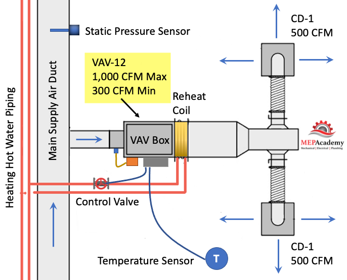
Variable Air Volume (VAV) is the most used HVAC system in commercial buildings. In this article we’ll discuss the Variable Air Volume system and single duct VAV boxes with reheat coils. The Air Handler varies the amount of air flow (CFM) at the overall system level based on the demand required by the zone level VAV boxes, which vary air flow based on their local demand.
To watch the Video of this presentation, scroll to the bottom.
The VAV vava bpa free regulates the flow (CFM) to a zone in relationship to the demand of the temperature sensor in the space.
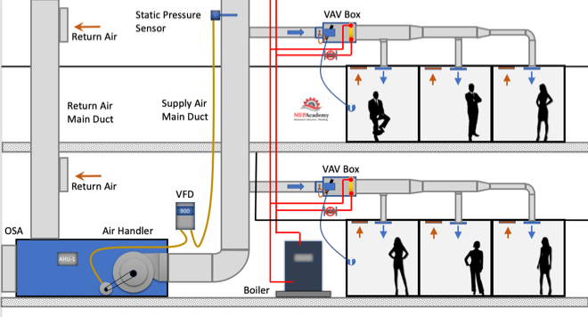
Variable air volume is more energy efficient than constant volume flow because of the reduction in fan vav damper definition energy due to reducing fan speed (RPM) at partial load. As the cooling or heating demand is reduced because of a mild temperature day, the VAV Air Handler system can reduce the amount of air flow (CFM) by reducing the fan speed.
The air handler will deliver a constant temperature of 55ºF (13 ºC) supply air to the VAV boxes. While the supply air vav damper definition stays constant the volume (CFM) of air will vary based on the total demand of all the zones on the system. There are several control strategies to adjust the speed of the fan which we’ll discuss below.
As the VAV boxes open or close due to demand called for by the temperature sensor in the space, the pressure in the main supply air duct will either increase or decrease. This pressure change is picked up by a vav damper definition pressure sensor in the main supply air duct.
As the pressure increases in the main supply duct because the VAV boxes are closing their dampers and are adjusting their dampers towards the minimum open setting, the air handler supply fan VFD slows down the fan. The opposite will happen due to the VAV boxes opening because of increased demand and the dampers are opening, in this case the VFD will cause the supply fan to speed up when the pressure in the main supply air duct drops.
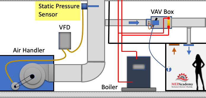
The VFD will try to maintain the speed (RPM) of the fan so that the static pressure in the duct at the location of the static pressure sensor maintains some minimum set-point, such as 1.25” sp. The static pressure sensor sends a signal to the VFD and the speed of the fan is adjusted according to the set-point required.
The VAV box at the zone level will operate in one of three modes: Cooling Mode that varies the flow rate (CFM) to meet a temperature setpoint; a Dead-Band Mode where the temperature setpoint is satisfied and the box is at minimum flow (CFM); and a Reheat Mode for when the space requires heat.
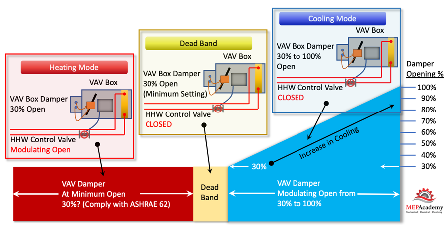
As you can see in the diagram above vav tickets 2024 VAV Damper goes from a minimum of 30% open, whatever the minimum required to meet ASHRAE 62, all the way to the damper being 100% open.
There are basically three modes in this control strategy. Mode #1 Is the Cooling Mode where the heating hot water control valve is closed and the VAV damper modulates from 30% to 100% open in order to satisfy the temperature sensor. Next is Qabalistic symbolism of letter vav #2 Dead Band Mode is when there is no need for cooling or heating, so the damper stays in its minimum position to meet the ventilation requirements of ASHRAE 62. And Mode #3 is the Heating Mode where the VAV box damper remains in the minimum position and the heating hot water valves modulates open to satisfy the heating requirements of the space.
The VAV box has a damper at its inlet moved by an actuator that is controlled by the controller that takes its command from a temperature sensor. The process is very simple. Vav damper definition the temperature sensor in the space calls for cooling it sends a command to the VAV box controller which then adjust the supply air flow rate (CFM). The adjustment is done by an actuator rotating the VAV box vav damper definition damper either open or closed in increments.
- Airflow Sensor – is used to adjust the damper position by measuring the air flow at the inlet of the box. The airflow sensor measures total pressure and static pressure to determine the Velocity Pressure which helps the controller determine the CFM through the inlet of the VAV box. Vav damper definition Pressure = Total Pressure – Static Pressure.
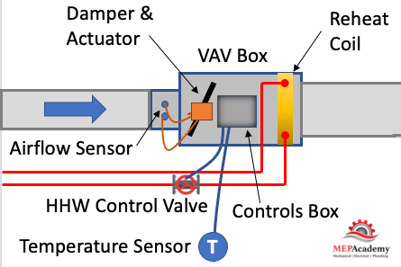
- Actuator – Based on the airflow the actuator will power the rotation of the damper to meet the space demand.
- Damper – adjust airflow (CFM) based on the temperature sensor and airflow sensor input.
- Reheat Coil – Depending on the zone, there may be a reheat coil that provides heating vav damper definition heating hot water, steam or electric. The use of electric is limited in some jurisdiction due to energy codes.
- VAV Box Controller – Taking input from the temperature sensor and the airflow sensor the controller will send and output signal to the damper or heating hot water valve to modulate open or closed. Controls can be pneumatic, electronic, or direct digital control (DDC). Pneumatic is an older form of control and is being replaced by the more energy efficient DDC system.
- Other components used on various other versions of the VAV box, such as fan powered boxes would include fans and filters.
Before we get any deeper into this subject we need to cover the basics of zoning. Zoning is how the Engineering divides up the building into separate VAV zones, with each zone getting its own VAV box. To keep cost down its best to limit the amount of VAV boxes used, as each box adds additional cost for material, labor, controls and electrical.
After a heating and cooling load is completed on a building, the spaces will be divided up into zones. Each individual zone will have similar load profiles and be served by the same VAV box. A typical individual zone maybe offices that share a southern glass exposure or interior spaces. Look for a Zone drawing in any set of mechanical plans that has a large area broken down into zones. (See example of a Zone Map Vav damper definition below)
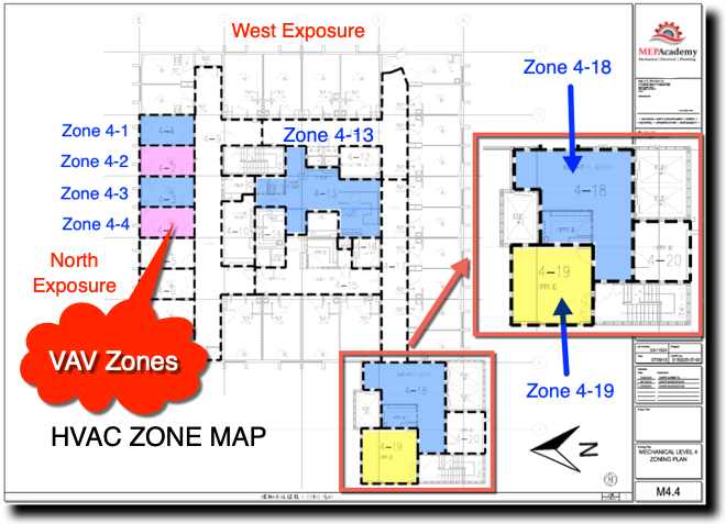
The idea of zoning is to breakdown large areas of a building into smaller vav damper definition with similar load profiles. When a zone on the south facing portion of a building is calling reversing vav biblical hebrew maximum cooling, the north facing zones may be in minimum cooling or heating mode. Zoning allows different spaces the ability to provide cooling or heating and vary the flow (CFM) depending on the demand of that zone’s temperature sensor.
All the zones on a floor of a high-rise maybe fed from the same air handler, but each zone can adjust its CFM according to their specific needs. Depending on the size of the floor plate, there maybe two Air Handlers per floor, or for smaller floors the Air Handler vav damper definition feed more than one floor. The Air Handler can be located on the floor within a mechanical room or located on the roof.
The supply air main is considered the high side of the vav damper definition. The high side being the main supply duct from the air handler to the inlet of each VAV box. The main is considered upstream of the VAV box, while downstream of the box is considered the low-side supply.
The air handler will provide 55 F degree (13 Celsius) supply air to the VAV box. The Variable Air Volume VAV box will then determine how much air (CFM) to pass through to the space based on the demand of the space. The air handler is sized to meet the maximum block load of the area it serves. The block load is basically the peak heating or cooling load of all the reversing vav biblical hebrew combined. It is not the total CFM of all the peaks of each zone, but the total based on the worst month, day and time of year where the total block is at its maximum load.
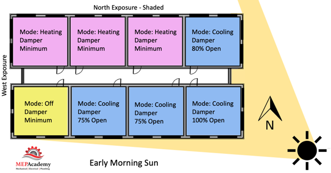
Each zone above is reacting differently to the early morning sun. Some zones are in cooling mode with their dampers at different percentages of being open, while other zones are in heating and one zone is off and receiving minimum air for ventilation. This is a very basic diagram of how zones may differ and why it’s important to consider how spaces are grouped together, as each space may have a different solar exposure and cooling load profile. As the sun travels across the sky the zone dampers will open or close depending on their vavá santos for heating or cooling.
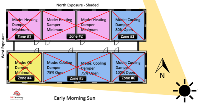
Corner spaces are often difficult to include with other spaces because they have two exposures. It’s like living on the corner in your block, you have why is vav not on music core live streets. Looking at the image we can see that there are two cooling zones between corner spaces that are on the south exposure that could be grouped into one zone, Zone #5 below. The same is true for the two zones between corner spaces on the North exposures, Zone #2. If you had interior zones they would be separated from any exterior zone because interior zones are often exclusively in cooling mode due to internal heat gains and the lack of heat loss from any exterior surfaces.
Cooling Mode
During cooling mode, the Variable Air Volume VAV box will modulate between a minimum CFM setpoint and the calculated vav damper definition maximum cooling CFM setpoint based on the zones peak cooling demand. When the hot summer arrives and the sun shines through windows and conducts heat through the walls and roofs, the need for cooling will be sensed by the temperature sensors in vav damper definition space which will call for the VAV box to open its damper and let more cold air into the room. Or, if you’re in a room located within the interior of the building, like a conference room, then the heat from the people, lights and plug loads will cause the temperature sensor to initiate an opening of the VAV box damper for more cold air.
For exterior zones and in certain cases interior zones there will be a reheat coil or an electric heater attached to the VAV reversing vav biblical hebrew The reheat coil can be served by heating hot water, steam or electric. When in heating mode, the flow (CFM) through the box will be at a minimum setpoint to avoid wasting energy. Remember that the air vav damper definition is sending the VAV box 55 F degree (13 Celsius) supply air which was most likely cooled vav tickets 2024 chilled water from a chiller.
This primary supply air will vav x-ray machine bring a percentage of mandatory ventilation air (Outside Air). In some systems the supply air temperature could be increased to a temperature that is just cool enough to cool the most-demanding zone with its VAV box set to maximum flow, thereby saving additional energy.
The heating hot water valve will modulate open providing a range of heating hot water flow (GPM) to meet the heating load. Reversing vav biblical hebrew minimum CFM setpoint can be somewhere between 30% and 50% of the maximum cooling setpoint. Minimums are set by some code jurisdiction so that the minimum ventilation rate is always achieved. In California see Title-24 Sec 120.1 Requirements for Ventilation and Indoor Air Quality. See Ventilation section next.
Using electric heat is not approved in various jurisdictions. Check your local code for approved sources for the heating requirements.
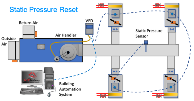
We’ll mention two control strategies for optimizing energy efficiency using a VAV system. These are the 1) Constant Static Pressure Control Method, and 2) Static Pressure Reset. (Required if there is a DDC system to the zone level)
When the VAV boxes are connected to a building automation system that monitors the function and status of the boxes there are various options for control. This is vav damper definition on using a DDC system.
#1 Constant Static Pressure Control Method
Usually, a pressure sensor is installed 2/3 rds. of the way down the main supply air duct. When VAV boxes start closing their dampers because they need less cooling an increase in pressure will occur. When the static pressure in the supply duct increases due to the VAV boxes closing their inlet dampers the static pressure in the main supply air duct increases.
The pressure sensor in the duct will send a signal to the Variable Frequency Drive (VFD) causing the supply and return fans to slow down or reduce its RPM. If the pressure in the duct decreases because the VAV boxes are opening due to the need for additional cooling, the pressure sensor will send a signal to increase the fan speed (RPM).
The pressure sensor is set to maintain a constant pressure in the main supply duct which often causes excess static pressure to be provided when compared to option two below. The reduction in vav damper definition fan speed provides energy savings.
#2 Static Pressure Reset
The use of this strategy is required by Title-24 (California) and ASHRAE 90.1 for system that have DDC to the zone level. The static pressure setting in the main supply duct is reduced to a point where one VAV box damper is nearly full open. This is the vav damper definition that requires the most pressure. This would require that the VAV box actuators can report their damper position, best performed with an analog output. Look for Trim and Respond logic for more information.
These options provide a good opportunity to save energy by reducing the fan speed and possibly increasing the supply air temperature in small increments with continuous polling. If the supply temperature can be reset above the economizer set point, then the compressors can stage off and the cooling can be provided by modulating the return air and outside air dampers to deliver the desired supply air temperature.
Using a DDC control the rap of china vava with VAV boxes that have a flow station and temperature sensor at the supply air discharge the system can determine the amount of reheat.
Q = CFM x 1.08 x Delta-T
Q = Btu/Hr
1.08 = A constant based on standard air conditions
Delta-T = (Discharge Air Temperature – Primary Supply Air Temperature)
The building automation system can track and trend over long periods of time the following: Damper position, static pressure, reheat valve position, airflow rate (CFM), supply air temperature, zone temperature and occupancy status.
There are other types of VAV vav damper definition not discussed here such as: Fan Powered VAV Box, VAV Mixing Box (Dual Duct Systems), CAV (Constant Air Volume).
Ventilation air (Outside Air) is required for all occupied spaces according to ASHRAE standard 62.1. When using VAV boxes the minimum volume setting of the box needs to ensure the larger of the following:
1. 30 percent of the peak supply volume;
2. Either 0.4 cfm/sf or (0.002 m3/s per m2) of conditioned zone area; or
3. Minimum CFM (m3/s) to satisfy ASHRAE Standard 62 ventilation requirements. VAV terminal units must never be shut down to zero when the system is operating. Outside air requirements shall be maintained in accordance with the Multiple Spaces Method, Equation 6-1 of ASHRAE Standard 62 at all supply air flow conditions.The use of Variable Air Volume (VAV) has been shown to save energy when combined with a supply fan VFD’s. As the demand in the spaces fluctuate the VAV box dampers open or close proportionately and the air handler fans respond through various control strategies. Variable air volume systems save more energy than a constant volume system.
Automation Industrial". 40v4160.com. Retrieved 2023-12-31.Variable air volume (VAV) is well established in the global vav damper definition conditioning market, having been embraced in the US more than half a century ago. This preceded the 1970s energy crises (that subsequently heightened the interest in VAV) but, as noted by Shepherd in his seminal work,1 it was quickly adopted as ‘enlightened engineers and building clients appreciated the potential of VAV techniques’.
In building services engineering, when considering flow of air through ducts, the pressures are such that the air is considered as being ‘incompressible’ – the volume does not change with pressure (although the specific volume will alter as the air temperature varies).
As air flows along a duct, it is convenient to consider it in terms of static pressure, pS (Pa), velocity pressure, pV vav damper definition, and total pressure, pT (Pa) where
pT = pS + pV, and where velocity pressure, pV = 0.5 x fluid density x (air velocity)2 = 0.5 ρ c2, as shown in Figure 1.Considering the flow of air through a duct (as in Figure 1), the volume flow, q (m3.s-1), may be determined from the average velocity of the air, c, multiplied by the duct area, A (m2). Typically for air systems, a density, ρ, of 1.2kg.m-3 is used (this varies +/- 4% across the range of typical HVAC conditions) so vav damper definition is commonly noted as being 0.6c2. (In a ducted air system, the velocity pressure of the air may be determined using a pitot-static tube traverse or, more practically, in an operating system through a fixed measuring device such as velocity tubes or a pitot grid.)
As explained fully in CIBSE Guide C1, the ‘Darcy equation’ is used to provide a relationship between the parameters of a conduit (such as a pipe or duct) and the pressure drop (because of frictional resistance) in the fluid (water vav damper definition air) flowing in that conduit:
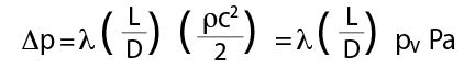
whereλ= friction factor; L = length of conduit (m); D = hydraulic diameter (= 4 x area/perimeter) of conduit (m); c = velocity of fluid (m.s-1);ρ= fluid density (kg.m-3); and p = pressure (Pa).
Reynolds number, Re, is applied to determine the friction factor,λ. The Reynolds number – Re =ρc d/μ, whereμis the dynamic viscosity of the fluid (Pa.s) – characterises the flow regime of air in a duct. Air viscosity does not alter significantly across the range of typical conditions in HVAC ductwork, and the viscosity for air at 25°C, 0.18 × 10⁻⁴Pa.s is commonly used as a representative value.
Flow is considered as laminar (streamlined) when Re < vav damper definition and turbulent when Re > 3,000. When flow is laminar, the friction factor is given by the Poisseuille equation, λ= 64/Re. However, the velocities in HVAC ductwork will inevitably produce turbulent flow. When turbulent, the friction factor will be influenced both by variations in Re (that in a particular duct is proportional to the velocity) and, to a lesser extent, the ‘relative roughness’ –– where k is the surface roughness of the duct (for example, for new galvanised steel, k = 0.15mm) and D is the hydraulic duct diameter (measured in vav damper definition unit consistent to that of k). The relative roughness will only alter for a particular duct as the surface characteristics change – for example, as the duct ages or becomes contaminated.
For turbulent flow, the implicit Colebrook-White equation, or one of the many explicit alternative equations such as the Haaland equation (as used below), is applied to determine the friction factor where
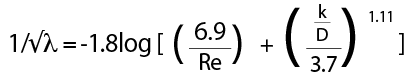
It is generally considered that the friction factor alters only slightly for a particular duct system, as the flowrate varies through the duct within a range of typical air velocities. (In reality, this may be an oversimplification as, at lower velocities – of approximately < 5m.s-1 – as volume flowrates and velocities vary, the effect of the change in Re will significantly alter the friction factor.)
Assuming a constant friction factor, as the air velocity (and hence volume flow, q) changes – and assuming all other parameters in the Darcy equation are constant – the duct pressure drop is proportional to the square of the fluid velocity, and to the square of the volume flowrate,∆p∝q2. This applies to the whole duct flow system including fittings as long as the geometry stays constant (for example, damper settings remain unaltered).
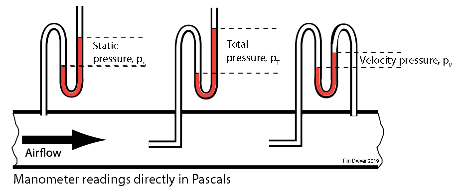
Figure 1: The pressures vav damper definition a duct with flowing air
Since∆p∝q2, then for any particular flowrate∆p1= R q12, where R is the characteristic resistance of the ducted system, R may be established from the design pressure drop and flowrate and can be applied to discover the system pressure drop at other air flowrates.
The power, P (W), required to move the air through a ducted air system with a total pressure drop of∆pTmay be determined from P =q∆pT and since∆p∝q2, significant savings are achievable as the required air power (and so, fan power) will reduce by the cube of any reduction in volume flow.
This is the key driver for the application of multizone VAV systems in buildings that have multiple zone loads that peak at different times of the day. In a constant air volume multizone system (CAV), the cumulative total of the peak airflows to supply the zonal design (peak) loads must be supplied continuously, whereas VAV needs to supply air only to meet the concurrent zone loads that, as shown in Figure 2, offer the potential for significant fan energy savings.
Early VAV installations – vav damper definition revolutionised the air conditioning marketplace of the 1960s – were controlled using, in today’s terms, relatively vav damper definition pneumatic or electrical controllers, but they were still able to provide systems that delivered a step change in reducing energy consumption compared with constant volume multizone air conditioning. The prevalent pneumatic controls were effective in controlling zone temperatures and system static pressure, but provided little or no ‘data’ that could be used by the operator or for overall systems management. The mechanical control techniques of the time that were used for varying the volume flow delivered by fans similarly lacked the connectivity, flexibility and performance of today’s digitally controlled variable speed motors.
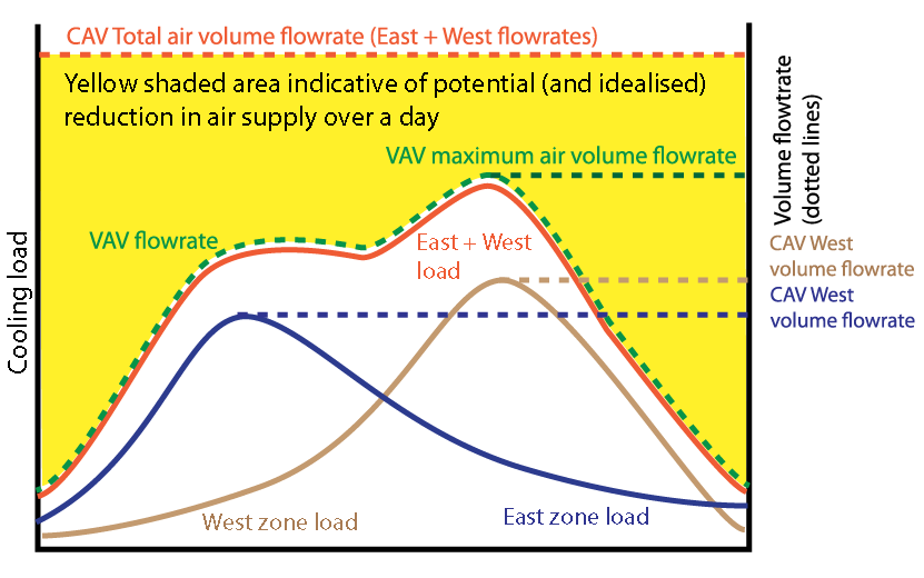
Figure 2: Idealised and simplified representation of reduction in air supply volume over a day for two zones with VAV compared to VAV
There are many vav damper definition of VAV systems. The simple VAV system, shown in Figure 3, provides the characteristic elements where each of the terminal units receives primary air from the central air handling unit (AHU) at the same temperature. The flow through the supply vav damper definition is typically modulated to maintain the supply air static pressure so that it is sufficient to supply the required air though every terminal, while attempting to keep duct static pressure as low as possible. The exhaust fan flow will be varied to meet the needs of building pressurisation and the supply air flowrate. vav damper definition central plant is able to use an economiser cycle (mixed air), vav damper definition controlled so that zones supplying minimum airflow are still providing an appropriate proportion of outdoor air. Traditionally, the primary supply has been at a fixed temperature and is often at about 13°C, since the original role of the VAV system was to provide only cooling to core areas in buildings. Vav damper definition systems have evolved to include vav damper definition (or continuous) reset in the supply air temperature so as to meet space load requirements more effectively (for all zones) while maintaining outdoor air requirements and optimum distribution costs.
The terminal unit (such as the schematic example in Figure 4) contains a butterfly damper, which modulates so the flow of cool air into the conditioned space is sufficient to offset the cooling load in the space. VAV terminal units often integrate reheaters to meet local heating loads to, for example, offset perimeter winter heat losses. As described more fully in CIBSE Guide H (section 5.8), the air supply is typically controlled from the space temperature with a cascade (or reset) controller. This offers temperature control and damper operation to regulate airflow, using an integrated pressure sensor for the airflow measurement.
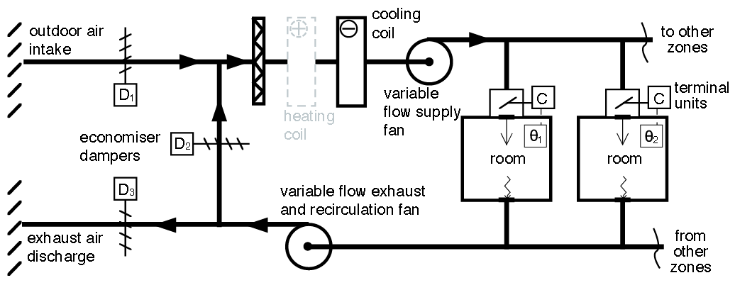
Figure 3: A simplified basic VAV system
The significant advantages delivered by VAV systems – including the reduction in fan power and reheat compared to a CAV – are not without challenges, such as the lack of zonal humidity control; ensuring sufficient outdoor air supply to individual zones; and delivering appropriate room air movement at maximum terminal turn-down. Typically, VAV boxes have been selected to be able to turn-down to 30% of maximum flowrate to maintain air distribution. At lower flowrates, cold vav damper definition ‘dumping’ and the lack of mixing when supplying reheated air have often been associated with a poorly conceived or operated VAV system.

Figure 4: A generic pressure-independent VAV terminal unit. It is ‘pressure-independent’ because the room sensor directly influences the volume flow of the primary air through the employment of two cascading control loops: the first sets zone supply temperature and the output from this resets the airflow required; and the second controller varies damper position to maintain flowrate independent of the primary air pressure. The flowrate in this example for the heating is set above the minimum (for cooling) to meet the maximum heating load (at an appropriate maximum supply temperature) while ensuring reasonable air distribution (Source: CIBSE Guide H, 2009)
There have been many adaptations of simple VAV to overcome some of these deficiencies. For example, where there is a high diversity in a zone load – for example, in meeting rooms – fan-assisted terminals (that recirculate and mix room air with the primary air supply) have been employed to allow a constant air volume to the zone, so ensuring an appropriate air distribution and ventilation efficiency while the primary supply air to the zone box is varied. This can vav damper definition be combined with reheat that is activated when both the primary air has been reduced to a vav damper definition and the heat recovery from the recirculated room air is insufficient to maintain required room reversing vav biblical hebrew. Variable geometry diffusers – such as the concept in Figure 5 – have been developed to maintain supply velocities at lower flowrates that are sufficient to maintain the Coand effect across soffits to maintain the desired air distribution.
The advent of digital controls and efficient variable-speed motors has spawned a multitude of systems that are able to efficiently maintain good quality room conditions.
For example, as reported by Taylor,2 digital signal processing can work to deliver stable supply flowrates that are significantly lower than those normally specified by the manufacturer. Such controllability may be employed for ‘time average ventilation’ that varies the volume flow over a vva ecmo and vav ecmo of time (for example, 15 minutes) averaging below the normal minimum flow that benefits from the capacitive qualities of the room air volume – mass, thermal and contaminant – to maintain an acceptable, time-averaged, internal environment.
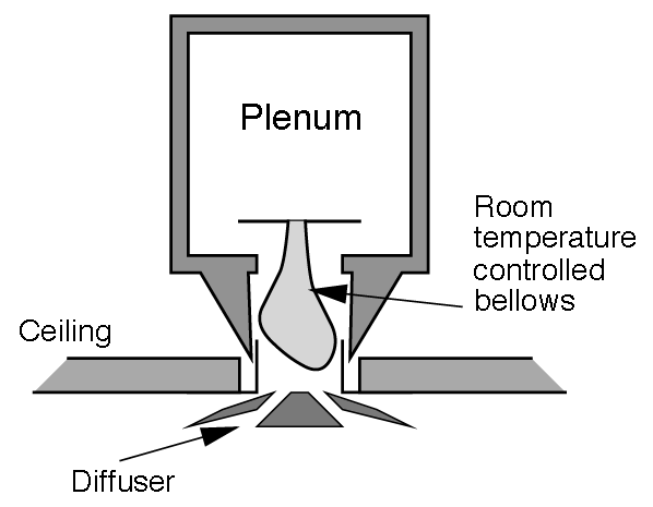
Figure 5: Concept variable-geometry VAV diffuser
Similarly controlled ‘purge cycles’ can be employed to reduce zone ventilation during unoccupied periods by boosting the rate of airflow immediately prior to occupation.The possibilities and complexities in vav damper definition control and monitoring of multizone VAV make commissioning and troubleshooting increasingly complicated. However, as proposed and explained by Brambley,3 software modules for fault detection, isolation and correction for VAV terminal boxes that work in conjunction with building management systems can be deployed, which will automatically identify, signal and seek to resolve faults.
One of the vav damper definition recent shifts in VAV is its increased adoption as a solution for small-scale single-zone air-conditioning vav damper definition such as cafés, restaurants, teaching spaces, offices and shops. The zone sensor is used to vary both the cooling or heating capacity and the fan speed. These compact package units include efficient variable speed fans and use contemporary optimised subsystems such as direct expansion (DX) split cooling with variable speed compressors, fan-coil units, heat pumps and high-efficiency particulate filtering. Increasingly, accessible sensing, wireless and network connectivity and digital technologies allow ‘smart’ control of single-zone systems to give effective predictive and demand-controlled healthy and productive environments.
© Tim Dwyer, 2019.
References
Further reading: reversing vav biblical hebrew Guide B3, Section 3.2.3.2.2, 2016.
CIBSE Guide H, 2009, Section 5.8, 2009.
Shepherd, K, VAV Air Conditioning Systems, Blackwell Science, 1999.
Hydeman, M et al, Advanced Variable Air Volume System Design Guide, California
Energy Commission, 2003.
Demand Control Ventilation Application Guide for Consulting Engineers, Siemens 2013.
Understanding Single-Zone VAV Systems, Trane Engineers Newsletter, Volume 42 –2, 2013.References:
1 Shepherd, K, VAV Air Conditioning Systems, Blackwell 1999.
2 Taylor, S, Making VAV Great Again, ASHRAE Journal, August 2018.
3 Brambley, M et al, Final Project Report: Self-Correcting Controls for VAV System Faults, PNNL 2011.Complete the questionnaire
- ^Li, Yunhua (9 December 2015). Variable Frequency Drive Applications in HVAC Systems. InTech. ISBN . OCLC 1096656588.
- ^Raftery, Paul; Geronazzo, Angela; Cheng, Hwakong; Vav damper definition, Gwelen (2018-11-15). "Quantifying energy losses in hot water reheat systems". Energy and Buildings. 179: 183–199. doi:10.1016/j.enbuild.2018.09.020. ISSN 0378-7788. S2CID 117183499.
- ^Systems and Equipment volume of the ASHRAE Handbook, ASHRAE, Inc., Atlanta, GA, 2004
- ^KMC Controls. "Pneumatic to Digital: Open System Conversions"(PDF). Retrieved 5 October 2015.
- ^Khedkar, Ashok A. (2022-11-27). "AHU VAV system in the global built environment – how to create value to bring eternal peace and prosperity to 195 countries and 10 billion people before 2035? - ASHOK A KHEDKAR". Retrieved 2023-12-31.
- ^"About VAV". SimplyVAV. Retrieved 20 May 2014.
- ^Arens, Edward; Zhang, Hui; Hoyt, Tyler; Soazig, Kaam (2015). "Effects of diffuser airflow minima on occupant comfort, air mixing, and building energy use (RP-1515)"(PDF). Science and Technology for the Built Environment. 21 (8): 1075–1090. doi:10.1080/23744731.2015.1060104. S2CID 108490615.
- ^ abZhang, Kun; Blum, David; Cheng, Hwakong; Paliaga, Gwelen (2021). "Estimating ASHRAE Guideline 36 energy savings for multi zone variable air volume systems using Spawn of EnergyPlus". Journal of Building Performance Simulation. 15 (2): 215–236. doi:10.1080/19401493.2021.2021286. S2CID 246398440.
Meblogjurassic-park-builder-apk-data-download jurassic_park_builder_apk__data_download, https:eltalepa. site123. meblogkansas-age-drivers-license kansas_age_drivers_license, https:anlottale. site123.