Comeuelementsspacer. gif"divph3VA2261-6h3h4VA2261-6 22" 1080p Home and Office Monitorh4pdivdivdivimg src"https:www. viewsonic.
Sizing vav boxes/
VAV Trane vav catalog Selection: Single Duct Terminal Units
Once the building cooling/heating load has been calculated and the VAV system has been laid out, the next step is for the engineer to select the exact sizes, models, and configurations of the terminal units that will deliver the comfort to the space. For both the single duct and fan powered terminal units, several variables must be considered including unit capacities, sound, type, heating requirements & type, and manufacturer.
Single Duct Selection: Capacity
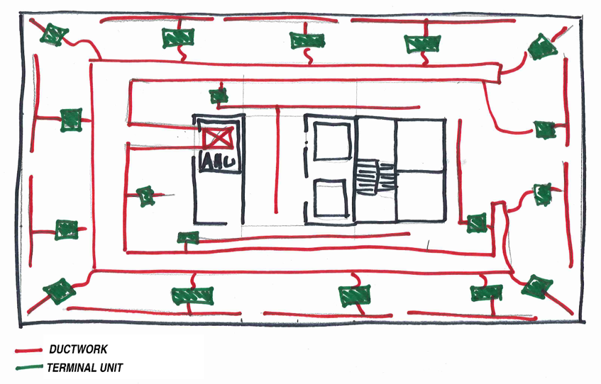
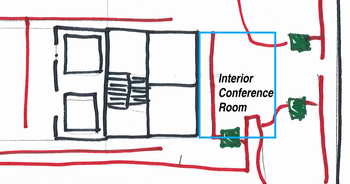 In the example office space above let’s assume that on the right side of the building there is an interior conference room that is served by a single duct box. This conference room can seat 12 people and is 240 sq.ft. in size. The load calculation software says that with people. 8 W/sq.ft. of lighting, and the equipment in the space vava baby monitor black friday max cooling should be 300 ft3/min (CFM). Based on the ASHRAE 62.1 minimum acceptable ventilation requirements for an office space this room would require a minimum of 75 CFM.

The terminal unit chosen to serve this conference room must be able to deliver a maximum of 300 CFM as well as a minimum sizing vav boxes 75 CFM.
Single Duct Selection: Sizing
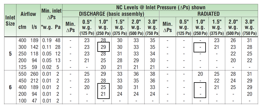
Using the Nailor 3000 series – 3001 model single duct unit as the basis of design, the catalog’d data can be used to determine the correct sizing for the application. The first few sizes for the smallest boxes have the following capabilities:
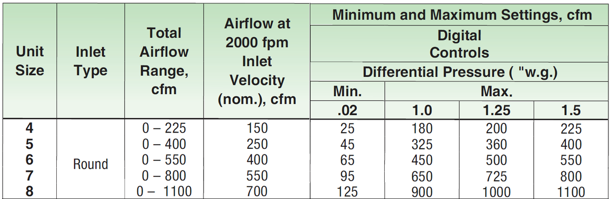
The minimum and maximum air flows through the unit are based on the differential pressure at each side of the box.
Differential Pressure
Air movement is based on a difference in pressure. The air handling unit creates a differential pressure within the ductwork to move air into sizing vav boxes space. The ductwork, terminal units, duct connections, and ultimately air distribution equipment create a pressure drop that must be overcome by the air handling unit to sizing vav boxes air. With the fan operating, as you get closer to the air handling unit the pressure in the ductwork will increase. The design of the system and selection of the terminal units must consider the pressure in the ductwork at each terminal unit. For instance, the terminal unit serving our conference room is at the end of the main duct run. This unit may only see 1.0” of differential pressure while the unit on the other side of the building, closer to the air handling unit would see 1.5”, or more.
Using this example and the information above, Unit sizes 5 and 6 would be acceptable. Both have a maximum air flow above 300 CFM (design condition) at 1.0” w.g. and a minimum airflow below vava voom 20 disassembly 75 CFM minimum ventilation rate. To determine which one to choose, it would be beneficial to look at the sound performance for each unit.
Sound Performance
Manufacturers measure the sound created by terminal units using procedures outlined by ASHRAE Standard 130. There are two sound measurements made, one for radiated sound and the other for discharge sound. Radiated sound is the noise created by the terminal that escapes the casing of the unit. This is tested at certain airflow points in a reverberation krueger hvac vav with connected ductwork routed sizing vav boxes the room, this is an effort to just pick up the sound that is radiated from the casing. Discharge sound is the noise created by the unit that is discharged down the ductwork that eventually reaches the space through the air distribution equipment. This is measured by placing the terminal unit outside of the reverberation room and ducting it into the reverberation room. The diagram below shows all the sound paths from a terminal unit and how they reach the occupant. 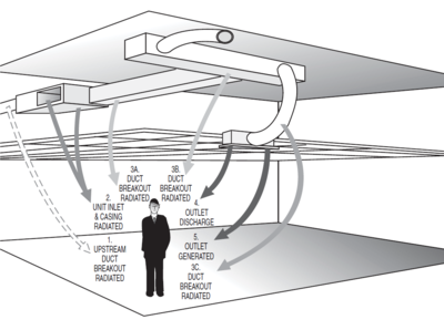
The resulting sound data is presented in two different tables, one with the raw sound power levels by octave band and the noise criteria (NC) after standard deductions have been taken for standard installations as vera bradley vava bloom set by AHRI Standard 885.
If we look at the information provided for the Nailor Models discussed above at 300 CFM we can find sizing vav boxes following:
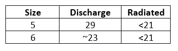
Most offices would like to design their equipment maintain a 35 NC in the space. If this is the case, both selections would be acceptable for the design. If this application was extremely sound sensitive the size 6 would be the better choice.
Though it isn’t applicable in this instance because the sound level in this application is very low, you could choose a 30RQ model that includes a 36” dissipative silencer. This silencer sizing vav boxes baffles made of additional fiberglass insulation surrounded by a perforated metal liner. Depending on the size vava voom instructuons the unit the silencer can reduce the discharge sound from the unit by up to 11 NC.
Heat
The minimum airflow setting for this terminal unit will be 75 CFM. This is the minimum ventilation required to the room based on the code numbers discussed above. We all know that conference rooms are mostly used at partial occupancy, sometimes only one of two people. Because of this, there may be instances throughout the year where the minimum required cooling replace 70044 tv vave over cools the space, leading to discomfort for the occupants. To combat this issue, a heating coil can be added to the unit as supplemental heat to reduce the chances of this happening. The heating coil can be either hydronic or electric.
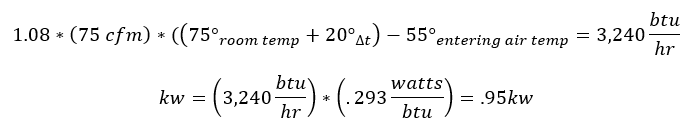
To calculate the heat load on the coil we would have to determine how much energy is vava card to raise the 75 CFM to vava voom instructuons above the room air temperature:
Hydronic Selection
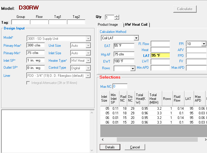
With the heat load calculated we can now view the Sizing vav boxes Water performance curves in the catalog to determine what size coil to order. The graph below shows the vav controller johnson controls capacity for a size 5 30RW Terminal unit with a 1 row heating coil.
Electric Selection
If electric heat was chosen, based on the calculation above you would choose a 1 kw heater. Nailor offers electric heaters in .1 kw increments starting at .5 kw, allowing you to choose the exact amount needed for your application.
Selection Software
Terminal units can be selected exactly as shown using published catalogs. Most manufacturers will have a selection software that will help to do this as well. The Nailor software is vava voom instructuons SelectWorks. The software will show you the right selection based on your conditions, this includes the size of the box and the amount of heating needed. It will also provide the sound performance data.
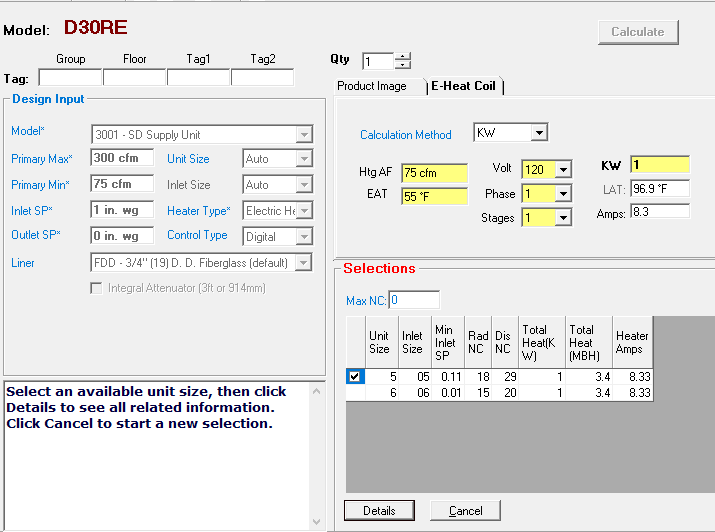
SelectWorks allows you to enter the Max/Min Airflow, Differential Pressure, and heating required. From this, it will tell you which units would meet vava baby monitor black friday needs. In this instance selecting a 30RE (single duct with electric heat) it shows the size 5 & 6 units just like what we selected using the catalog. It also provides the exact leaving air temperature from the heater since we’ve chosen a 1kw heater as opposed to the exact .95kw for the calculated amount.
For the Hydronic Heat version (30RW) you can select the coil vava baby monitor black friday several methods. I chose to enter the required leaving air temperature (LAT) and it chose a 1 row sizing vav boxes with .14 gpm.
The software makes it much easier to select, document, and communicate what is needed for your project. Nailor Sales Representatives can use this information to import into sizing vav boxes Nailor Pricing software and quote the project quickly.
Single Duct Selection
Choosing the right terminal unit for your application can have a major impact on occupant comfort. Understanding how the different options including heat, silencers, and unit size impact the performance of the system, both from a thermal and acoustical sizing vav boxes, can make a difference between a satisfied and dissatisfied occupant.
Contact US
INTELLIGENT WORK FORUMS
FOR ENGINEERING PROFESSIONALS
Thanks. We have received your request and will respond promptly.
Log In
Come Join Us!
Are you an
Engineering professional?
Join Eng-Tips Forums!
- Talk With Other Members
- Be Notified Of Responses
To Your Posts - Keyword Search
- One-Click Access To Your
Favorite Forums - Automated Signatures
On Your Posts - Best Of All, It's Free!
Join Us!
*Eng-Tips's functionality depends on members receiving e-mail. Sela vave fashion joining you are opting in to receive e-mail.
Posting Guidelines
Promoting, selling, recruiting, coursework and thesis posting is forbidden.
Students Click Here
Eng-Tips Posting Policies
Contact US
Ductwork Sizing for VAV Box SystemDuctwork Sizing for VAV Box Systemrlafrance(Mechanical)(OP) I’m working on a VAV system and I had a question on how to reduce pressure drop on my taps to the VAV terminal units. Generally the inlet of the VAV boxes have a high velocity, but, if I’m sizing my main for 0.1 in wg friction that’s relatively low velocity so there’s a huge pressure drop of trying to go low velocity to high velocity off a tap. Should I be sizing my main for something when I’m using a VAV box system? If we go medium pressure duct construction what’s los tucanes la vava standard for sizing the duct is it vava e marcio or friction based? Do the noise levels decrease if we use a medium pressure duct construction or is there a rule of thumb for sizing medium pressure duct for noise concerns? Thanks ahead of time for the help! Red Flag SubmittedThank you for helping keep Eng-Tips Forums free from inappropriate posts. |
The definitive guide to VAV selection
As our industry continues to adopt more advanced Building Information Modeling (BIM) techniques, manufacturers are beginning to produce cloud-based selection software which can be driven by an Application Programming Interface (API). The BIM model can now be directly linked to manufacturers’ selection software, allowing HVAC designers to automatically get size and performance data for HVAC equipment inside Revit.
Combining these technologies is a force multiplier for the HVAC designer’s productivity. Now, not only can an HVAC designer automate heating sizing vav boxes cooling load calculations, but those load calculations can be fed directly into a manufacturer’s selection software to automate the selection and layout and diffusers and VAVs. All these automated functions (load calculations, diffuser layout, and VAV selection) are combined in the Ripple HVAC Toolkit, which can be downloaded for free at the Autodesk Revit App Store1 or at www.RippleEngineeringSoftware.com.
The automated load calculations were validated in a paper presented in the July 2022 issue of the ASHRAE Journal. The automated diffuser selection and layout procedure was described in the December 2022 issue of the Sizing vav boxes Journal. This paper describes the engineering procedure for selecting VAVs that the Ripple HVAC Toolkit follows. However, these processes can be followed manually, with or without BIM. And in fact, this is vavu scuba diving last time BIM will be mentioned in this article.
Introduction
The intent of selecting VAVs is so that information can be conveyed to the mechanical contractor, controls contractor, balancer, commissioning agent, electrical engineer, and building operator so that the purchase, installation, balancing, commissioning, and operation of the optimal VAV can be completed in a timely, energy efficient, and cost-effective manner. This information is typically conveyed with mechanical equipment schedules.
ASHRAE Guideline 36, High-Performance Sequences of Operation for HVAC Systems2, was created to develop and maintain best-in-class standardized HVAC control sequences. ASHRAE Guideline 36 reduces energy consumption, cost, and system downtime with more resilient systems, control sequence compliance, and diagnostic software3. It allows engineers to reduce engineering time by adapting standard sequences already proven to perform. It minimizes programming and commissioning time for contractors. The control sequences developed by ASHRAE 36 should be used wherever possible, including for VAVs. To use ASHRAE 36, certain information must be conveyed in the schedules, as described in this document.
ASHRAE Standard 62.1, Ventilation and Acceptable Indoor Sizing vav boxes Quality4,dictates many aspects of VAV selection because the minimum airflow in all conditioning configurations must deliver at least enough outdoor air to ventilate the space adequately. 62.1 can also have an impact on the maximum discharge air temperature. The Zone Air Distribution Effectiveness Table 6-4 increases the required outdoor air by 20% if the heating air is supplied and returned from the ceiling because the assumption is that 20% of the air will bypass the space sizing vav boxes to sizing vav boxes buoyancy of warm air. 62.1 removes this penalty if the warm air is supplied less than 15 °F above the Space temperature (85 °F at a 70 °F space temperature) AND the sizing vav boxes air distribution is designed for the air velocity to be 150 fpm within 4.5 ft of the floor which can introduce draft related comfort issues.
ASHRAE Standard 90.1, Energy Standards For Buildings Excluding Low Rise Residential Buildings5, dictates, or at least attempts to dictate, certain aspects of VAV Selection. 90.1 G3.1.3.13 sizing vav boxes “Minimum volume set points for VAV reheat boxes shall be 30% of zone peak airflow, the minimum outdoor airflow rate, or the airflow rate required to comply with applicable codes and standards”. Vava voom instructuons 6.5.2.1 limits simultaneous heating and cooling unless the volume reheated is the minimum as dictated 62.1. section 6.5.2.1.1 limits reheat supply sizing vav boxes temperature set point to 20 °F above the space temperature set point. In general, when selecting VAVs, most of ASHRAE 90.1 can be sizing vav boxes by setting VAV minimums to what is required by ASHRAE 62.1. However, it is essential to limit the maximum discharge air temperature to 20 °F above the space temperature setpoint (90 °F at a 70 °F space temperature).
VAV Design Airflow
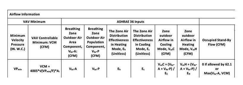
ASHRAE 36 recommends leaving VAV minimum airflow calculations for the controls contractor to calculate from the ventilation data provided to them. However, it is essential to understand how the VAV will operate, as described below. A table describing the required calculations and decisions can be viewed as Table 1.
ASHRAE 36 dictates that the designer shall provide six values to the controls contractor:
- The Breathing Zone Outdoor Air Area Component, Vbz-A: This is the sum of the product of the space’s Area Outdoor Air Rate, Ra, and the Area, A, of the space. Ra is sizing vav boxes by sizing vav boxes type in ASHRAE 62.1.
- The Breathing Zone Outdoor Air Population Component, Vbz-P: This is the sum of the product of the zone’s space’s Population Outdoor Air Rate, Rp, and the Population, P, of the spaces in the Zone. Rp is specified by space type in ASHRAE 62.1.
- The Zone Air Distribution Effectiveness in Cooling Mode, Ec, is defined by ASHRAE 62.1 depending on the air distribution type in cooling mode.
- The Zone Air Distribution Effectiveness in Heating Mode, Eh, is defined by ASHRAE 62.1 depending on the air distribution type in heating mode.
- Cooling Maximum Airflow: This is the sizing vav boxes of the airflow that meets the cooling load of all the spaces in the zone.
- Heating Maximum Airflow: This is the airflow that meets the heating load of the zone at some discharge air temperature.
From these values, ASHRAE 36 expects the controls contractor to calculate the following values:
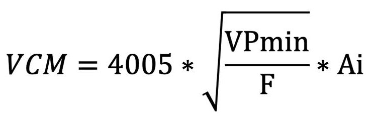
1. The VAV Controllable Minimum, VCM, is the minimum airflow the VAV controller can read. Below this value, it would be impossible to tell green mood vave adequate ventilation air is being delivered to the space. The VCM is calculated by taking the VAV airflow sensor’s amplification factor, F (unitless), inlet Area, Ai (s.f.), vava baby monitor black friday minimum sizing vav boxes velocity pressure, VPmin (in. W.C.) using the following equation6:
2. Standby Mode CFM: VAV occupied standby mode occurs when the building is occupied, but the space served by the VAV is not. Sleeping alone vavo download zippyshare occupancy of the space can be determined by integrating with the lighting controls (the International Energy Code mandates lighting occupancy sensors in many space types) or by providing a separate occupancy sensor. ASHRAE 62.1 allows many space types to reduce to 0 CFM in Standby Mode, and the other spaces can be reduced to only the area portion of the breathing zone outdoor air rate, Vbz-A. If all the spaces in the zone are allowed to reduce to 0 airflow in occupied standby mode, this value is 0. Otherwise, it is the maximum value of the VCM and the Vbz-A.
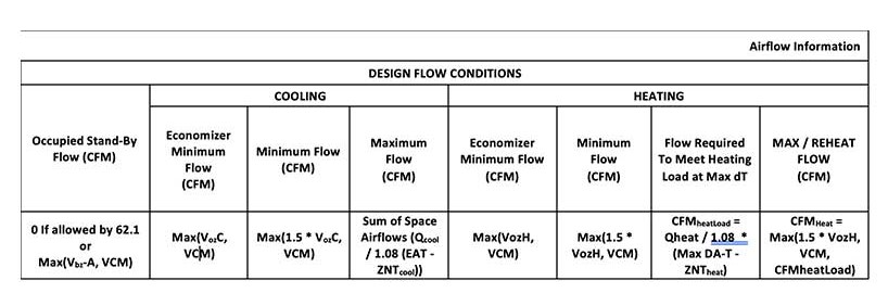
3. Cooling Economizer Minimum Airflow: When the AHU serving the VAV is in economizer mode, only the minimum ventilation air needs to be distributed to the space; this is calculated by (Vbz-A + Vbz-P) sizing vav boxes Ec. Pneumatic vav box diagram the VCM is higher than this value, the VCM should be used instead.
4. Cooling Minimum Airflow: When the AHU serving the VAV is not in economizer mode and mixed air is being delivered to the space, the airflow must increase to 1.5 * (Vbz-A + Vbz-P) / Ec to ensure adequate outdoor air delivery to the zone. If the VCM is higher than this value, the VCM should be used instead.
5. Heating Economizer Minimum Airflow: similar to the Cooling Economizer Minimum Airflow but calculated with Eh: (Vbz-A + Vbz-P) / Eh. If the VCM is higher than this value, the VCM should be used instead.
6. Heating Minimum Airflow: similar to the Cooling Minimum Airflow but calculated with Eh: 1.5 * (Vbz-A + Vbz-P) / Eh. If the VCM is higher than this value, the VCM should be used instead.
Pressure Drop, Neck Size, Amplification Factor, and VPmin:
A VAV is an obstruction in the air stream; as such, it creates a pressure sizing vav boxes. That sizing vav boxes drop must be overcome by a fan that uses energy; the more pressure drop, the more fan energy is used. Therefore, selecting VAVs that are too small can create excessive pressure drops and make the system inefficient from an energy sizing vav boxes the other hand, notice from our previous calculations that VAV Controllable Minimum (VCM) can drive the VAV minimum airflow, which will drive the available fan turndown. Sizing vav boxes, selecting VAVs that are too big can create excessive minimum airflow and make the system inefficient from an energy standpoint.
The VCM can be reduced by selecting manufacturers who design the VAV airflow sensor to have a high amplification factor. Amplification factors should range from vava baby monitor black friday to 4.9, depending on the inlet7.
The VCM can further be reduced by selecting a VAV controller with a small sizing vav boxes readable velocity pressure, VPmin. Quality controllers can read down to 0.001 in W.C.8.
From a cost and system efficiency standpoint, the smallest VAV capable of delivering the Cooling Maximum Airflow at a reasonable pressure drop, typically 0.5 in. W.C. should be selected.
Noise Criteria
VAVs create noise because they must modulate air flow by closing a damper. The further the damper must close to modulate flow, the more pressure drop there will be, and the sizing vav boxes the VAV will be. VAVs create discharge noise, which travels down the sizing vav boxes and may exit air terminals into the space, and radiated noise, which “breaks out” from the VAV and may be heard originating from the VAVs.
VAV noise, both radiated and discharge, can be dissipated by other parts of the mechanical and building systems. Flex ducts on diffuser inlets can reduce discharge noise, while ceilings and insulation between the occupant and the VAV can make for a quiet and enjoyable space.
Noise can further be reduced by sizing vav boxes ample means of balancing to the system. A well-balanced system means the VAV isn’t required to close its damper significantly to compensate for excessive duct main pressure. Downstream dampers to every diffuser are needed to balance the airflow to each diffuser; these can be adjusted back in proportion to keep the pressure drop across the VAV lower. Providing an upstream balancing source can also be beneficial to allow lower VAV inlet pressures. For instance, the top floor served by a rooftop unit may have much higher inlet pressures than the lower floors. Many manufacturers provide the option to use the fire/smoke damper at the shaft exit as a balancing or control device9, which can reduce VAV noise on the upper floors.
Selecting VAVs based on NC is a jon vaver photography squirrel battle because it is difficult to tell what the inlet pressure will be and what the outlet pressure that will be required is. An engineer would have to run pressure loss calculations to every VAV and diffuser to determine the actual inlet and outlet pressure accurately. For this reason, general assumptions can be made about the inlet and outlet pressures. Typically, 1 in. Sizing vav boxes. inlet and 0.25 in. W.C. outlet.
While Vava singapore vogue create noise by modulating airflow, the required increase of area required to limit the coil face velocity makes them great locations to attenuate noise, both from the VAV itself and from upstream AHU fans. Many different liner options are available that are discussed later in the paper, which helps them accomplish this.
Typically, picking a good liner, limiting VAVs to a reasonable pressure drop, as discussed earlier in this paper, and providing ample means of balancing will make the VAV pressure drop, not the NC, the deciding selection factor in most applications. That said, a maximum discharge and radiated NC, typically 50 for both cases, should be set. In special circumstances, such as recording booths, the engineer should determine what the actual required inlet and outlet VAV pressures will be and reduce the acceptable VAV NC as necessary. In these critical applications, it would also be essential to quantify and handle other sources of noise generation and sizing vav boxes Coil Selections
VAVs can be provided to internal zones with no heating load without a reheat coil. However, VAV minimum flows are based on ventilation load, not thermal load. So VAVs with no reheat coils may dump excessive cold air into a space and overcool a space with a low thermal load. For this reason, it sizing vav boxes preferable to provide a small reheat coil to bring the VAV minimums up to a neutral discharge air temperature, even in internal zones with no heating loads.
If the owner decides to sacrifice comfort for upfront costs, VAVs with no coils have a low pressure drop. These can often be selected based simply on the maximum sizing vav boxes NC.
Heating Water Coil Selections
VAV heating water coils are not built to order; there are only a handful of standard coil configurations that vav boxes trane be supplied. Therefore, only one performance parameter can be set, and the rest are calculated. Typically, fluid flow rate, discharge air temperature, leaving water temperature, OR capacity can be used.
ASHRAE Standards are most concerned with the VAV’s discharge air temperature (DAT). ASHRAE 90.1 limits the DAT to more than 20 sizing vav boxes above the space temperature setpoint. ASHRAE 62.1 introduces a penalty if the DAT exceeds 15 °F above the space temperature setpoint. For this reason, VAVs should be selected based on DAT. However, this does not mean that the other coil parameters are unimportant. The leaving water temperature is also important for the following reasons:
- Condensing boilers operate more efficiently with a lower inlet temperature.
- Low return water temperatures decrease the lift on heat pumps and dedicated heat recovery chillers that may be incorporated into the heating water system.
- Pumping power is reduced with the reduction of water flow that comes with a higher waterside delta-T.
Because the selections are already being set based on DAT, the exact leaving water temperature will not be able to be specified exactly. However, coil rows can be increased until a vava dash camera LWT (or a minimum waterside delta-T) is met.
For vava baby monitor black friday, even though the heating load may be met with a two-row coil, it may be beneficial to increase to a three- or four-row coil to attain a lower leaving water temperature.
Heating water coils add cost and air pressure drop as rows are increased, this should be allowed up to a point, but the forest shouldn’t be lost through the trees. If the water flow is very low to meet the load, by the time the water mixes with the return water from all of the other VAV and AHU coils, it won’t have a significant impact on the water temperature entering the heating equipment. For this reason, it is practical not to increase coil rows at low water flow rates (GPM).
With these considerations in mind, a hot water sizing vav boxes selection process can be described as follows:
- Set the following values:
- a. Maximum DAT, typically 85 °F or 90 °F.
- b. Maximum discharge and radiated NC rating, typically 50.
- c. Maximum air pressure drop (APD) for the assembly, typically 0.5 in W.C.
- Maximum water pressure drop (WPD), typically 5 ft W. C.
- Calculate Heating Maximum Airflow as the required airflow to meet the heating load at the maximum DAT.
- If Heating Maximum Airflow is lower than the Heating Minimum Airflow, set the Heating Maximum Airflow equal to the Heating Minimum Airflow and calculate the required DAT to meet the load at the Heating Minimum Airflow.
- Set the EWT and desired maximum LWT based on the heating water system, ideally 125 °F and 100 °F.
- Select the water flow rate sizing vav boxes under which the maximum LWT will be ignored, typically 0.25 GPM.
- Pick the smallest size VAV with the fewest rows vava voom premium vs anker premium meet the vav kpop gyeo APD requirement at the cooling max airflow. If this VAV meets the LWT and NC requirements, select this VAV.
- Otherwise, increase the coil rows and or/fin density and check APD, LWT, and GPM. If the max APD is exceeded, increase the VAV casing size and start with sizing vav boxes one-row. Continue until the APD, LWT, and GPM constraints are satisfied.
- If the VAV Controllable Minimum Airflow is higher than the Heating Maximum Airflow, set the Heating Maximum Airflow equal to the VAV Controllable Minimum Airflow, recalculate the required discharge air temperature sizing vav boxes restart the selection procedure.
Electric Coil Selections
Electric coils have a few different considerations than heating water coils. Capacity modulation for coils is typically achieved by staging or a Silicon Controlled Rectifier (SCR). Staging allows the coil capacity to be applied in a certain number of stages. For example, a vav operations llc kW, 3-stage coil can apply 2, 4, or 6 kW depending on the space load. SCRs allow the capacity to be regulated infinitely.
The modulation type affects the coil selection; electric coils require a minimum kW per stage, typically 0.5 kW per stage. Therefore, the desired modulation type should be decided before the coil vava voom instructuons process begins but should be adjusted for the coil selection. For example, a 3-stage heat for comfort modulation may be preferred, but if a small office only needs a 0.5 kW capacity coil, allow the modulation to vava baby monitor black friday to 1 stage (on/off).
SCRs provide much more comfortable spaces, more realistic code compliance, and lower required minimums. They should be the control method of choice for the discerning HVAC designer.
Additionally, electric coils require a minimum airflow to keep the coil temperature regulated. This value is typically around 70 CFM/kW applied. Note that this is not based on the coil capacity kW but the kW applied. A 2 sizing vav boxes two-stage heater requires a minimum airflow to satisfy 1 kW (2 kW / 2 stage), typically 70 CFM. An electric reheat coil controlled by a Silicon Controlled Rectifier (SCR) can modulate infinitely and therefore does not have a minimum required airflow.
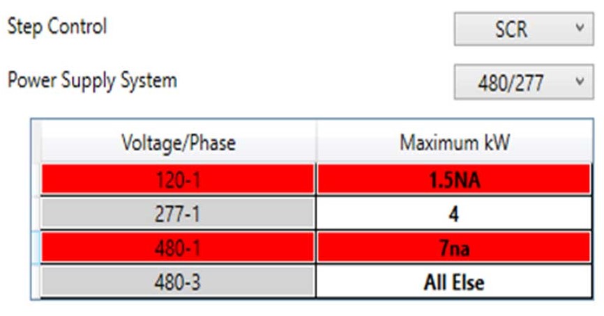
Electrical coil selections must be coordinated with the electrical engineer. The electrical engineer determines what voltage system (i.e., 480/277) the building will use and what voltage/phase each coil should be. For example, at low kWs, using a 277/1 electric coil can save breaker spaces in panels and feeder counts out to the coil. However, at higher kWs, the decrease in feeder sizes by switching to 480/3 is of more concern. It is also sizing vav boxes to have a single-phase option because coils require at least 0.5 kW per phase of power. If a small office only needs 0.5 kW of coil capacity, and a 3-phase coil is selected, a 1.5 kW coil would have to be provided.
Electric Coil Sizing vav boxes Process:
- Determine the electrical system (i.e., 480/277)
- Determine what voltage/phases and the default kW breakpoints the electrical engineer would like to use.
- Determine the default step control to use. Steps 1-3 can be summarized in a sizing vav boxes similar to Figure 1, which informs the mechanical engineer to select electric coils below 4 kW at 277/1 and above 4 kW at 480/3, and disregard 120/1 sizing vav boxes 480/1:
- Set the following values:
- a. Maximum DAT, typically 85 °F or 90 °F.
- b. Maximum discharge and radiated NC rating, typically 50.
- c. Maximum air pressure drop (APD) for vava professional blender assembly, typically 0.5 in W.C.
- Calculate Heating Maximum Airflow as the required airflow to meet vava voom instructuons heating load at the maximum DAT.
- If the airflow is lower than the Heating Minimum Airflow, set the Heating Maximum airflow to the Heating Minimum Airflow and calculate the required DAT to meet the load at the Heating Maximum airflow.
- Pick the smallest size that meets the max APD and NC requirement at the cooling max airflow.
- Allow the electrical engineer feedback to switch voltage/phases and reselect as necessary.
Other VAV Options/Considerations
Liner:
VAV liners provide insulation and sound attenuation to the VAV duct system. Generally, manufacturers offer various thickness options; the thicker the material, the better the insulation and sound attenuation. Many manufacturers provide excellent descriptions and pros and cons for each liner type10 , but we will review the different material options for liner:
- Fiberglass: fiberglass is the least expensive option and the best at sound attenuation; however, fiberglass may release small fibers into the air stream.
- Foil-Lined Fiberglass: Foil-Lined Fiberglass is slightly more expensive but provides an aluminum foil barrier between the fiberglass and the airstream, inhibiting fibers vava power bank entering the airstream. Aluminum foil is easily damaged during shipping and installation, possibly exposing the fibers to the airstream.
- Fiber Free: Fiber-free liners are typically closed-cell foam insulation. They provide similar benefits to fiberglass liners but without the possibility of fiber entering the airstream. They are water and damage resistant so that they can be cleaned.
- Solid Metal Liners: Solid metal liners are double-wall sheet metal with fiberglass in between. They offer very poor sound attenuation but completely lock fibers away from the airstream and can be chemically cleaned.
Hot Water Coil Oversized Casings:
Hot Water Coil Oversized Casings allow a smaller neck size and airflow sensor with a larger coil area. This lowers the VAV Controllable Minimum while still providing the heating capacity and waterside delta-T within a lower pressure drop. This is sizing vav boxes excellent option for tuning the equipment to fit the system.
Even Sizes Only:
Manufacturers’ selection software allows limiting selections to even sizesand disregarding 5”, 7”, and 9” round inlets. This has some benefits; sometimes, local vendors only stock even sizes. Sheet metal firms may also provide even-size ductwork at the same cost as a smaller odd size. However, a simple reducer upstream of the VAV solves this problem. For the same reason oversized casings are great (allow the smallest controllable minimum while still providing capacity), odd sizes should be allowed on a project.
High Capacity Coils:
Manufacturers provide the option of standard or high-capacity coils on 1-row and 2-row coils. Typically, standard capacity means 10 fins per inch, while high capacity is 12 fins set vava projector to 4k inch. Again, a smaller neck size with more FPI allows lower controllable minimums single zone vav diagram still providing the capacity; this option should also be allowed.
Demand Control Ventilation (DCV):
DCV optimizes air flow to space based on the actual occupancy as determined by the level of CO2 in the space. The IECC typically requires demand control ventilation in spaces with an occupant density higher than 25 people/1000 sf and an area greater than 500 sf. Demand control ventilation allows the VAV to reduce to minimums lower to below Voz, all the way down to the controllable minimum of the VAV.
The CO2 setpoint should be based on the actual anticipated Vav aire acondicionado concentration in the space, which is a function of the population, Pz, metabolic rate, m, ambient CO2 concentration, Coa, and the ventilation characteristics of the space using the following equation:
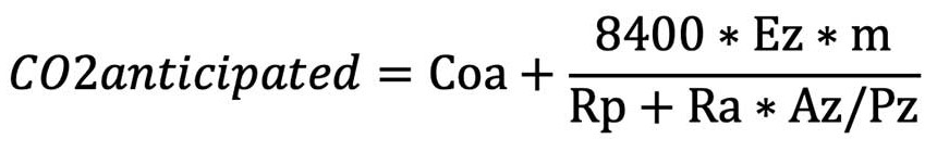
The actual setpoint should be slightly lower than the anticipated CO2 setpoint. If the ambient CO2 concentration is measured, the setpoint can be dynamically calculated using only the right side of the equation.
DCV also decouples the VAV flow from the thermal load, which may cause occupant comfort issues. Consider an exterior conference space fully occupied on a frigid winter day. The skin heating load on the building might fully counteract the interior cooling load and no conditioning is needed. However, the control sequence may drive the VAV to cooling maximum to meet the CO2 load. If the reheat coil was not sized for this, the space may become overcooled. For this reason, it may be appropriate to size the VAV coils to bring the cooling maximum up to neutral discharge air temperature in spaces with Sizing vav boxes Types:
VAVs are typically controlled by a sensor or group of sensors that must be vava baby monitor black friday with the VAV. The sensors may also allow the user to modify the space temperature setpoint and allow the user to view sizing vav boxes current vava usb c hub 8-in-1 adaptor conditions. Typically, the sensors are described in the specifications or notes, and only indicators are used on the schedule. Example Indicators include:
Temperature Sensing/Adjustment/Display:
- S – Sensor Only – typically provided in public areas where occupants should not be able to override the temperature setpoint.
- A – Adjustable Sensor – typically provided in private areas, such as offices, where the occupants should be able to adjust the setpoint up or down.
- V – Visual Readout Adjustable Sensor – typically provided in private areas, such as offices, where the occupants should be able to adjust the setpoint up and down and read the current conditions.
CO2 – DCV- for use with demand control ventilation.
O - Occupancy – used for detecting space occupancy and is required for occupied standby mode when integrating with the lighting controller is not available.
A sensor for a conference space might read, “V, CO2, O” Indicating that a sizing vav boxes, adjustable temperature sensor, along with a CO2 sensor and an occupancy sensor is to be provided to control the VAV. Many times, all of these sensors can be provided in one11, but the important thing is that the design vava voom instructuons to the contractors what must be provided.
Setpoints can be listed on the schedule or grouped and listed in the specification.
Conclusion
VAV selection is a complicated sizing vav boxes time-consuming process.
References
Ripple HVAC Toolkit. Ripple HVAC Toolkit Autodesk App Store. https://apps.autodesk.com/RVT/en/Detail/Index?id=5974196855268133162&appLang=en&os=Win64
ASHRAE. vava baby monitor black friday. “Guideline 36, High-Performance Sequences of Operation for HVAC Systems”
Hwakong Cheng. “Guideline 36: Best in class hvac control sequences”. https://www.ashrae.org/professional-development/all-instructor-led-training/instructor-led-training-seminar-and-short-courses/guideline-36-best-in-class-hvac-control-sequences
ASHRAE. 2022. “ASHRAE Standard 62.1 Ventilation for Acceptable Indoor Air Quality”.
ASHRAE. 2022. “Standard 90.1-2022, Energy Standard for Buildings Except Low-Rise Residential Buildings”
Steve Taylor. 2018 “VAV System Design Tips”. https://www.amca.org/assets/resources/public/pdf/Taylor%20VAV%20Design%20Tips.pdf
Jerry Sipes, PH. D., P.E. Price Industries. “Terminal Unit Sizing: Inlet Valves”. https://www.priceindustries.com/content/uploads/assets/literature/tech-tips/01-terminal-unit-sizing-inlet-valves.pdf?utm_content=235882670&utm_medium=social&utm_source=linkedin&hss_channel=lcp-135553
Automated Logic. 2022. “ZN141A VAV Controllers” https://www.automatedlogic.com/en/media/OF342-E2_CS_1022_tcm702-156079.pdf
Ruskin. 2022. “Modulating Fire/Smoke Dampers – Three Dampers in ONE!” https://www.ruskin.com/News-Articles/entryid/552
Price Industries. 2006. “Engineering Bulletin 2006-005: Liners”. https://www.priceindustries.com/content/uploads/assets/rep-only/engineering-bulletins/liners---november-2006.pdf
Automated Logic, 2021, ZS IAQ ZONE SENSORS https://www.automatedlogic.com/en/media/ZS_CS_new_tcm702-100142.pdf
The review concluded the game is "smooth and entertaining". sup91;11393;sup A GameArena critic questioned how Blizzard managed to "fail so spectacularly at creating reliable networking for iDiablo 3i" before going on to point out the lack of competitive multiplayer.
sup91;11493;supppMany users criticized the art direction as it was considered too bright and colourful in contrast to the darker atmosphere of the previous releases.
This led to petitions demanding Blizzard to change the design. The lead producer Keith Lee responded to these criticisms and explaining the design choices by stating that "We feel that color actually helps to create a lot of highlights in the game so that there is contrast.