In documenting these processes in an ongoing way, the authors seek to contribute to the understanding of artistic practice as research within the contemporary academic landscape. pdivdivdivh3Primary Sources in Music Production Research and Education: Using the Drexel University Audio Archives as an Institutional Modelh3divpWith Drexel University in Philadelphia acquiring the Sigma Sound Studios Collection in June 2005, an opportunity arose to establish this resource as a basis for research into modern music production techniques, recording technology and archival techniques as they relate to multi-track audio recordings.
Sigma Sound Studios was the paramount recording studio in Philadelphia from 1968 to 2003 and was instrumental in the creation of what became known as the Sound of Philadelphia. Using this example as a model, this paper will outline how an educational institution can best preserve and use multi-track collections for music production research and will include examples from the collection as well as discuss the complications of keeping a commercial recording collection.
br The Sigma Sound Studios Collection consists of 6119 magnetic tape-based recordings in twelve different recording formats.
Duel duct vav/
Dual Duct Variable Air Volume ADU
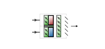
Dual duct variable air volume (DDVAV)) systems are used to obtain zone temperature control by mixing the cold and warm air in various volume combinations. The fan is sized for the anticipated maximum coincident hot or cold volume, not the sum of the instantaneous peaks. This system has an advantage of a true single path VAV system, except for warm port leakage. When cold air is modulated for control before mixing, it operates similar to the VAV induction when mixing occurs without hot deck reheat. It is similar to a reheat system when mixing occurs while the hot deck is using the reheat coil. It uses duel duct vav energy than a true VAV system, but less than a constant duel duct vav dual duct system.
General
Name
This is a read-only label that is automatically generated by the software and which incorporates the name of the zone in which the ADU is located.
Maximum damper air flow rate
The design maximum volume flow rate (in m3/s or ft3/min) specified for the DDVAV ADU.
Zone minimum air flow fraction
The duel duct vav flow rate to the zone duel duct vav the system is operating specified as a fraction of the Maximum Damper Air Flow Rate. The minimum zone fraction is normally specified to meet the minimum ventilation requirement for the occupants.
Operation
Availability schedule
This is the schedule that determines whether or not the unit is available for each timestep of the simulation. A schedule value greater than 0 (usually 1 is used) indicates that the unit can be on during the timestep. A value less than or equal to 0 (usually 0 is used) denotes duel duct vav the unit must be off for the timestep .
Variable Air Volume Systems
Since different spaces have different rates of heat gain and heat loss, it is impossible for an HVAC system that delivers the same temperature of air at a fixed volume to every space
to provide comfort conditions for all of them. Therefore, heating and cooling must be supplied at varying rates to different zones of the building. A zone is a space or group of spaces in a building with similar requirements for heating and cooling. All rooms in a zone can duel duct vav supplied with the same temperature supply air at the same flow rate.

SINGLE ZONE SYSTEM
The first HVAC systems were single zone systems (Figure 3). These systems treat the building as a single zone. They deliver air from a central air handling unit at a constant volume and a varying temperature (CV-VT). The central air handling unit in any HVAC system is the equipment in the mechanical room or on the roof that conditions the primary supply air and delivers it to the spaces.The single zone system is still used in residences and in small commercial buildings. The single zone system is effective in a small building because the heat gain and heat loss for different areas may not vary a great deal.

MULTIZONE SYSTEM
The multizone system (Figure 4) was an early system that was designed to meet the varying needs of different zones. It has a separate supply air duct to each zone in a building. There is a heating coil and a cooling coil in the central air handling unit. Both coils are in operation at duel duct vav same time. Dampers after the coils mix the hot and the cold supply air to the temperature needed to satisfy each zone.When heating and cooling occur at the same time it is called bucking because the heating and cooling coils are working against each other. The supply air to each zone is mixed to a temperature somewhere in between the hot and the cold supply air. The multizone system uses too much energy to heat and cool the air at the same time.
Because they waste energy, multizone systems are no longer being installed. They are generally banned by local building codes throughout the country.
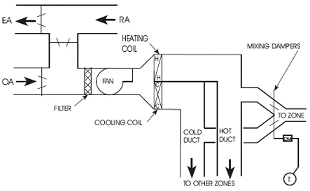
DUAL DUCT SYSTEM
The dual duct low pressure system (Figure 5) was also designed to meet the comfort needs of different zones. A dual duct system has two separate supply ducts from the HVAC unit to the outlets 樹脂成形 商社 vave the spaces. One duct supplies cold air, and the other supplies heated air. In this system both the heating and cooling coils operate at the same time, just as with the multizone system. The hot air and the cold air are mixed with dampers at each zone in order to obtain the air temperature needed for that zone. This system is intended to be constant volume-variable temperature (CV-VT).This system also uses too much energy because the hot air and cold vava suresh snake bite video are bucking each other. Therefore the dual duct system that mixes hot and cold air is now generally banned.
The dual duct system also has other problems. The vavá e gugu duct usually requires most of the supply air. This results in less flow in the hot duct at times and therefore a higher hot duct static pressure. When a zone called for heating, the high static pressure in the hot duct resulted in a high cfm that created drafts and noise in the conditioned spaces.
HIGH PRESSURE MIXING BOXES
To solve the problems of non-constant airflow rate in a dual duct system, a high pressure mixing box was developed. This replaced the mixing dampers. The mixing boxes control the cfm to a constant flow rate. The boxes change the system into a true constant volume-variable temperature (CV-VT).
The dual duct mixing boxes require a high static pressure to operate - usually a minimum of 1.5 inches wg. The system itself generally requires about 3.0 inches wg duct pressure to operate properly. The high fan horsepower duel duct vav to maintain the high static pressure, plus the bucking condition, means a high energy usage. The duel duct vav of operating the dual duct system was too high.
Another problem was that, because of the higher pressure often present in the hot duct, the hot air might flow back through the mixing box and into the cold duct. This could raise the air temperature in the cold duct so that the supply air could not cool the spaces adequately.
LOW PRESSURE REHEAT BOXES
Later, low pressure reheat units for the zones were developed. The supply air had to be cold enough to meet the needs of the duel duct vav with the greatest cooling load. The supply air to all other zones had to be reheated. There was no temperature control unless the boiler was operating. In the summer when the boiler was normally turned off, the system could only deliver cold air that was produced by the central cooling system. Often the conditioned spaces were too cold.
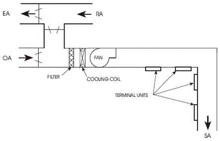
VAV SYSTEMS
Variable air volume (VAV) systems (Figure 6) were developed to be more energy efficient and to meet the varying heating and cooling needs of different building zones. A zone can be a single room or cluster of rooms with the same heat gain and heat loss characteristics.VAV systems can save as much as 30 percent in energy costs as compared to conventional dual duct systems. In addition, they are economical to install and to operate. Duct sizes and central air handling units are smaller and the design and installation is generally much simpler.
The main duct for a typical VAV system provides cooling only (at approximately 55°F). This is called primary air. Room thermostats control the amount of primary air delivered to each zone through modulating dampers for each zone. These dampers vary the volume vava suresh snake bite video air to each zone according to the cooling needs.
Early VAV systems varied the fan cfm output according to the total need of the zones. The fan was sized for the maximum probable load. As the air volume for the zones varied, the static pressure (SP) in the main duct tended to vary. An SP sensor in the main duct controlled the fan output to maintain a constant supply duct static pressure. The fan output was varied either by fan inlet vanes or by a damper at the fan outlet. These systems were variable volume-constant temperature (VV-CT)
Early VAV systems were cooling only, so a separate source of heat was needed for the outer rooms. This was usually supplied by perimeter heating in the rooms.
These early VAV systems were low-cost to install. However, depending upon the position of the zone dampers, the zones were subject to delivering too much cold supply air, which sometimes created drafts and air noise. These systems were very difficult to balance.
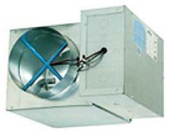
To better control the secondary air delivered to each zone, the VAV terminal unit was developed. A terminal unit is a small metal box (Figure 7) located in the supply air duct just before the outlet of each zone. A terminal unit is also called a VAV box, VAV unit, or outlet box.
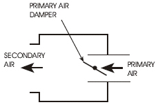
Each terminal unit (Figure 8) receives primary air from the central air handling unit at duel duct vav same temperature (about 55°F). The terminal unit contains a primary-air damper (a butterfly damper) which modulates (changes position) according to signals from the automatic control system. (A modulating damper is not just open or closed. It can be at any position in between.) The primary-air damper regulates the volume of cold primary air delivered to the terminal unit according to the needs of the spaces. This is also the volume of secondary air delivered to that space. Figure 8 shows only the duel duct vav features of a terminal unit.
The big advantage of VAV systems with terminal units duel duct vav that they are able to meet the duel duct vav requirements of different zones in a building without heating and cooling at the same time.
PRESSURE DEPENDENT OR PRESSURE INDEPENDENT
VAV systems are either pressure dependent or pressure independent.
The first VAV terminal units were pressure dependent. They had no means for limiting the quantity duel duct vav supply air.
In pressure dependent systems, the volume of air supplied by the terminal unit varies depending upon the static pressure (SP) in the primary air duct. The primary-air damper in the terminal unit is controlled by a thermostat in the space. However, the airflow through the damper varies according to the SP in the main duct. Terminal units that are close to the supply fan are likely to supply too much primary air. Terminal units that are farthest from the supply fan are not likely to supply enough primary air.
Pressure independent terminal units have flow-sensing devices that limit the flow rate through the duel duct vav. They can control the maximum and minimum cfm that can be supplied and are therefore independent of the SP in the primary air duct.
Almost all HVAC systems installed or retrofitted at present have pressure independent VAV terminals. Pressure independent systems can be balanced and will allow duel duct vav
correct airflow from each terminal.
VARYING FAN SPEED
Because each terminal unit regulates its primary air volume independently, the volume (cfm) of primary air delivered by the central air handling unit varies according to the demands of the terminal units in the system. This means that the supply fan in the central air duel duct vav unit must vary its output in order to meet the needs of duel duct vav the terminal units. If the primary-air dampers of most terminal units are full open, the cfm required for the entire system is high. If most terminal unit dampers are closed, the cfm required for the system is much less.
In many current systems, the rpm (speed) of the central supply fan is regulated by the control system to meet the changing demands of the system. A static pressure (SP) sensor in the primary air duct sends a signal to a controller that regulates the fan speed to maintain a constant SP in the primary air duel duct vav location of the SP sensor in the primary duct is titus vav boxes to the performance duel duct vav the system. It is best placed near the terminal unit that is most difficult to supply. This is the location that has the greatest pressure drop from the fan. If the sensor is placed too close to the supply fan, the SP in the supply duct will be too high during periods of low cfm demand.
IMPROVEMENTS IN VAV SYSTEMS
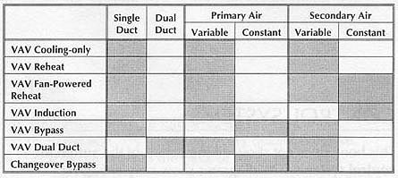
Early VAV systems were not highly duel duct vav by HVAC technicians. They were considered almost impossible to balance and to keep in balance. Today, pressure independent VAV systems are widely regarded as the best HVAC system design available. This change is largely a result of improvements in the terminal unit.Many VAV systems and terminal units have been developed to provide for the particular needs of a building. The following are the commonly used types:
Android. catalog-on-pc. html"divimg src"https:dl.