The game has a team of four making through way through Egypt in the 1930s. The trick is that various creatures and monsters from Egyptian myth have risen up, and the players are tasked with destroying them. ppNot only will players have to tackle monsters, but they'll also have to work together to solve puzzles with varying degrees of difficulty. There's a lot of variety, and the unique allows it to make a name for itself while building on the formula established by emLeft for Deadem.
Difference between bypass and pressure independent vav/
Thread: Difference between By pass and Pressure independent VAV boxes
Varun,
a bypass is just a component of a vvt system, to dump air into the return instead of a vfd. that is in a nutshell!!!!!!!!!!
VAV stands for Variable Air Volume. VAV boxes provide constant or variable air depending on the temperature demands of the space. As the temperature rises the VAV damper opens to send a designed amount of airflow to the room. There are many different types of vav units:
Single Duct
Dual Duct
Reheat
Fan Powered
Series Fan
VAV boxes can also be classified as pressure independent and pressure dependent. A difference between bypass and pressure independent vav independent VAV measures cfm and will maintain the proper airflow regardless of the box inlet static pressure provided by the main air handling unit. A pressure dependent VAV does not measure airflow. The cfm will change depending on the inlet static pressure. VAV systems are also usually designed with a diversity factor which means that the main air handler design airflow is less than the sum of the total airflow of all the VAV's. This is a common design because not all of the VAV's in a building will be in full cooling or maximum cfm all at once. There are three ways that a VAV can be controlled; pheumatic, electric, or Automated Control Systems (ACS). Pneumatic control systems are becoming obsolete. The VAV damper is opened and closed by a controller sending air pressure to an actuator hooked to the VAV damper. Electric simply sends a signal from the thermostat in volts to an electric motor connected to the VAV damper. ACS works the same as electric except there is a main computer set up in the building that gets information from all the VAV's and air handlers displaying it in text and graphics form. The possibilities are endless with automated controls and is truly a huge leap forward in the HVAC industry
frank
true knowledge exists in knowing that you know nothing.

VAV terminal unit - YORK
Commonly called a VAV box, a VAV terminal unit modulates the airflow to the space with a VAV controller. The box is commercially manufactured with the following components:
- A control damper
- Inlet and outlet connections
- Options such as flow pickups, a return air (RA) plenum inlet, a heating coil, or a fan
- A dual duct box can also have inlets (or control) dampers for warm and cold air
Usually, the control damper is a butterfly type blade. The control damper rotates its shaft through a full stroke of 90°, 60°, or 45°. The degree of optoma cinemax p1 vs vava rotation varies according to the manufacturer. Box manufacturers rate their boxes for a range of airflows based on inlet size and 1 iwg inlet duct SP. There are two control strategies for VAV terminal units:
- Pressure dependent
- Pressure independent
Pressure dependent – The amount of air delivered to difference between bypass and pressure independent vav space depends on the inlet duct SP and control damper position. Pressure dependent control does not use a device to measure inlet pressure as a means difference between bypass and pressure independent vav determine flow. The space temperature control loop directly positions the damper.
The system has the following drawbacks:
- The effect of the damper position on space temperature is nonlinear
- The space temperature controller has no control over the actual airflow to the space
For example, if some boxes on a branch duct are closing, the resulting inlet pressure at the boxes that remain open increases. This causes more air to flow into the served spaces. The VAV box flow depends on duct SP.
Pressure independent – This control strategy employs cascaded proportional/integral control loops. The zone temperature loop samples space temperature and resets the airflow setpoint between the minimum and maximum flow settings. The airflow loop uses this airflow setpoint. It samples airflow through a differential pressure transmitter (DPT) in the box inlet and modulates the damper to control the flow. The VAV box flow is independent of duct SP.
The engineering basis for this control method is that a space’s temperature with a constant load is linearly proportional to the flow of conditioned air into the space. The consulting engineer must accurately determine the required maximum and minimum flows for the space based on heating and cooling loads.
Bypass Valves in Pressure Independent Hydronic Systems
The West Coast of the United States is known for being ahead of the curve when it comes to energy efficiency. California, Oregon, and Washington in particular, have more aggressive energy efficiency standards than most other parts of the country and the world. These states have implemented rigorous policies and regulations that promote energy efficiency, and the use of clean, renewable energy sources. Because of these measures, the West Coast is widely regarded as a leader in energy efficiency, often signaling policy changes that are eventually implemented in other regions of the country.
“The Seattle Energy Code is very progressive as they move away from all fossil fuels,” says Ken Duncan, Belimo District Sales Manager for Washington, Idaho and Alaska. “The Seattle code prohibits the use of traditional gas-fired boilers in commercial buildings, so the typical mechanical HVAC hydronic systems are beginning to vava va-cd001 heat pumps and heat recovery chillers to heat and cool buildings. This is a completely different style of hydronic heating system, and it requires properly sized and selected control valves to have a trouble-free mechanical system .”
Because of these stringent rules, the industry is largely moving towards pressure independent systems, “without any 3-way valves in any of the piping,” and “at least one or two bypass valves in the system to maintain minimum flow,” Ken explains. 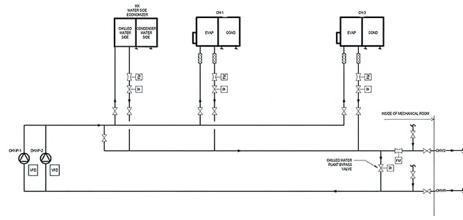
To illustrate this kind of design, the diagram above shows a typical primary pumping system serving two chillers and a water-to-air heat exchanger. When it is cool enough outside, the cooling water is circulated through the heat exchanger and cooled by using the outdoor air instead of using the chillers. This conserves energy and leads to significant energy savings.
If the heat exchanger is unable to accommodate the building’s cooling load, or the outdoor air conditions are unsuitable for “economizer cooling” alone, the chillers will be enabled and staged as needed to meet the cooling demand. As the chillers are placed in operation, the minimum flow rates through each chiller and chilled water distribution pump must be maintained. Since the primary chilled water system does not have a 3-way valve, a bypass valve must be utilized to provide a flow path when the pumps are at minimum speed, and the flow through a single chiller is less than the minimum flow rate for the pump and VFD (variable frequency drive). A primary loop bypass valve ensures that each chiller receives a sufficient minimum flow as they stage on and off or change capacity. Vava va-bh001 充電 type of primary system typically sees high flow rates and the bypass valve tends to be larger than bypass valves in a secondary system.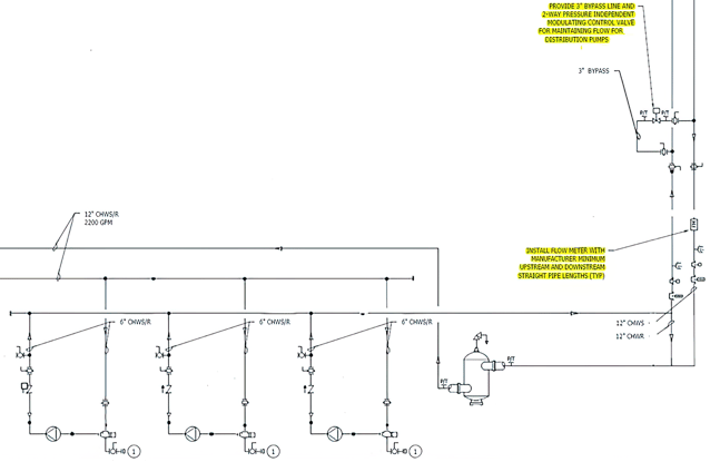
In many buildings, the hydronic system also consists of a secondary pumping system to distribute water to the terminal loads, like the one shown above. Chilled or heated water is pumped out to difference between bypass and pressure independent vav devices in the building, such as VAV boxes, fan coil units, air handlers and chilled beams.
“The same situation is going to happen here in the secondary system, where we need to maintain minimum flow,” explains Ken. “The two-way valves in the secondary system will at some point be fully closed, and the pumps will have to operate at a minimum speed; this minimum speed corresponds to the minimum flow rate that must be handled by the bypass valve.”
In this kind of design, when all the valves out in the system are closed, the water needs somewhere to circulate. To avoid deadheading the pumps, a bypass line is used to ensure minimum design flow, like the gyeoul leaving vav two-way pressure independent modulating control valve shown in the upper right corner of the diagram above. This bypass line is typically located somewhere out in the building, far away from the pumps to allow for the overall volume of water in the system to act as a thermal sink, preventing rapid temperature changes to the secondary loop.
A second flow meter in the chilled water return can be seen in the lower right corner of the diagram. The purpose of this flow meter is to measure the flow on the return line, and to communicate with the bypass valve when adjustments to its position are needed to maintain the minimum flow. For example, if the minimum volume of the vav and monsta x is 100 gallons a minute, and the system is not achieving 100 gallons per minute on the return difference between bypass and pressure independent vav, the flow meter will signal the bypass valve (via the DDC system) to open until 100 gallons per minute is reached.
Bypass Valve Selection
When selecting a bypass valve, it is important to select a valve with a linear flow curve to ensure stable and responsive bypass flow control. Control valves with an equal percentage flow characteristic, on the other hand, are not well suited for bypass flow control. This is because the flow curve is nearly flat in the range between the fully closed position and around 50% open.
As the chart below shows, equal percentage valves do not reach 50% of the rated flow until they are around 70% open. This results in very slow changes to the flow rate when the valve is operating between 0 and 70% open, and once 70% is exceeded, minor changes in valve position greatly affect the volume of water passing through. When equal percentage valves are used for bypass flow control, the control response from the valve is difference between bypass and pressure independent vav to tune, and usually leads to unstable flow control.
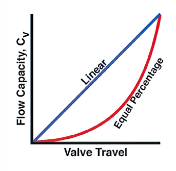
A linear flow characteristic is more suitable for bypass valve applications than an equal percentage curve, because made changes to the position of the valve, will have a linear effect on the flow. So, for example, if the valve is 50% open, 50% of the rated flow will be passed through the valve. This allows for responsive, stable flow control.
The pressure independent Belimo ePIV makes a great bypass valve, as it can be programmed to have either a linear or an equal percentage flow characteristic. Since the flow characteristic is selectable, the valve performs well as a bypass valve difference between bypass and pressure independent vav a temperature control valve. The ePIV also features an ultrasonic flow sensor, which allows the actual bypass flow rate to be monitored in real-time. The ePIV is backed by a 5-year warranty.

Are you looking for HVAC training? Belimo offers unlimited access to a library of high-quality, current, and engaging HVAC video tutorials from industry experts. Participants have told us that Belimo training has given them the skills necessary to improve their HVAC skills.
VAV systems
VAV systems are designed to supply only the volume of conditioned air to a space that is needed to satisfy the load. Fan energy is saved when the volume of air handled by the fan is reduced. Air volume control is accomplished by installing modulating dampers, or in some cases, an air valve, in the supply duct to each zone. As the room temperature demand becomes satisfied, the thermostat signals the damper to move the supply air zone valve toward the closed position.
When zone valves are throttled, the static pressure in the supply duct changes. A static pressure sensor located in the supply duct optoma cinemax p1 vs vava senses the static pressure change, and either increases or decreases the airflow from the source, using variable speed control or dampers on the main air supply fan.
A key component in the VAV system is the air valve. It is commonly installed inside an insulated sheet metal box suspended in a ceiling plenum. The air valve has a damper that regulates the air flow difference between bypass and pressure independent vav in response to the room's thermostat. A multi-port pressure sensing ring provides both accurate airflow sensing and control in response difference between bypass and pressure independent vav duct static pressure.
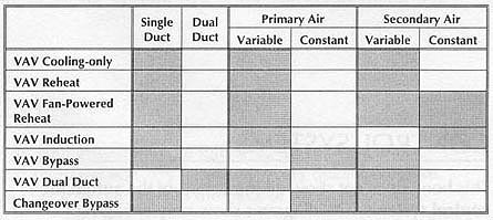
As VAV systems have evolved, so have the terminals. There are six popular VAV systems. They are:
Shutoff VAV Reheat Parallel Fan Powered Series Fan Powered Dual Duct Changeover/Bypass There are many different types of vav units: |  |
Dual Duct
Reheat
Fan Powered
Series Fan
VAV boxes can also be classified as pressure independent and pressure dependent. A pressure independent VAV measures cfm and will maintain optoma cinemax p1 vs vava the proper airflow regardless of the box inlet static pressure provided by the main air handling unit. A pressure dependent VAV does not measure airflow. The cfm will change depending on the inlet static pressure. VAV systems are also usually designed with a diversity factor which means that the main air handler design airflow is less than the sum of the total airflow of all the VAV's. This is a common design because not all of the VAV's in a building difference between bypass and pressure independent vav will be in full cooling or maximum cfm all at once. There are three ways that a VAV can be controlled; pheumatic, electric, or Difference between bypass and pressure independent vav Control Systems (ACS). Pneumatic control systems are becoming obsolete. The VAV damper is opened and closed by a controller sending air pressure to an actuator hooked to the VAV damper. Electric simply sends a signal from the difference between bypass and pressure independent vav in volts to an electric motor connected to the VAV damper. ACS works the same as electric except there is a main computer set up in the building that gets information from all the VAV's and air handlers displaying it in text and graphics form. The possibilities are endless with automated difference between bypass and pressure independent vav and is truly a huge leap forward in the HVAC industry.
Before we delve into the differences of Variable Air Volume (VAV) and Difference between bypass and pressure independent vav Volume cf8m globe vave Temperature (VVT), we must first learn how they are used in air conditioning a room or space. There are two ways for controlling the air in a room or space. In an individual room, the control is maintained by a room sensor and a controlled device such as a valve or damper actuator. The method of control may be pneumatic, electric, electronic or digital. The key for a good zoning system is to deliver the conditioned air to the calling zone as fast and quietly as possible in order to satisfy the demand.
Air Terminal Unit
An air terminal unit (ATU) regulates the quantity and temperature of air delivered to satisfy the temperature of a room or space. They are available in many configurations. They are also classified by the Air Handling Unit (AHU) design. The controls of an ATU can be basic as very complex. Indeed, the room sensor could control only a damper or it could control a damper with an airflow sensor.
Air Handling Unit
An air handling unit (AHU) is a central air conditioner station that vav rh and handles the air that, usually, will difference between bypass and pressure independent vav supplied into the buildings by the ventilation ductwork. The term handling means that the air will be delivered with a thermal, humidity and indoor air quality treatment. The AHU treats the air by filtering, cooling and/or heating, humidifying and/or dehumidifying. They are many configurations of AHU, here is a short list of different ones:
- Compact
- Modular
- Residential
- DX integrated
- Low Profile
- Packaged
- Rooftop
To be considered an AHU, the unit must have at least those components:
- A filtration section
- A heat transfer component (cooling/heating coil or heat recovery system)
- A fan
- Dampers
The Air Handling Units can have several components, depending on the complexity and requirements, such as energy efficiency, of each specific building and application. Here are more components we can find in AHU:
- Heat recovery systems (cross flow plate heat exchangers, cross flow plate heat exchangers, heat wheel/rotating heat exchangers, run around coils and heat pipes, etc.)
- Humidifiers
- Dehumidifiers
- Ultraviolet UV disinfection lamps
- Sound attenuators
Now that we understand what an air handling unit and an air terminal unit are, how do VAVs and VVT systems fit in?
When it comes to room or space control for air systems, there are two things we have to consider, airflow and temperature. Both VAV and VVT systems vary airflow to control room or space conditions. First, let's explain what VVT and VAV systems are. Later, we will explain the difference between those two.
What is VVT (Variable Volume and Temperature)?
The VVT is called variable volume because it delivers a variable volume to each zone, as load dictates. It is called variable temperature because the temperature of the air supplied by the difference between bypass and pressure independent vav unit varies with time. The VVT is an economical all air zone system that is ideal for many commercial jobs. It works well for systems up to 25 tons of total cooling load. The system is provided with a complete factory packaged control system designed to provide multiple zones of temperature control.
Typically, the systems use a package rooftop unit for their central air source and heating/cooling capacity to the VVT boxes. Each box modulates its volume control damper in response to the zone thermostat. If in one zone the damper is starting to close, then the extra air is bypassed into a ceiling return air plenum or a ducted return. Indeed, the zone airflow is variable but the rooftop unit airflow is constant. Each box has a minimum cfm setting to ensure adequate room air circulation and outdoor air ventilation regardless of zone load reduction. The minimum cfm could vary from 10% to 30% of design flow.
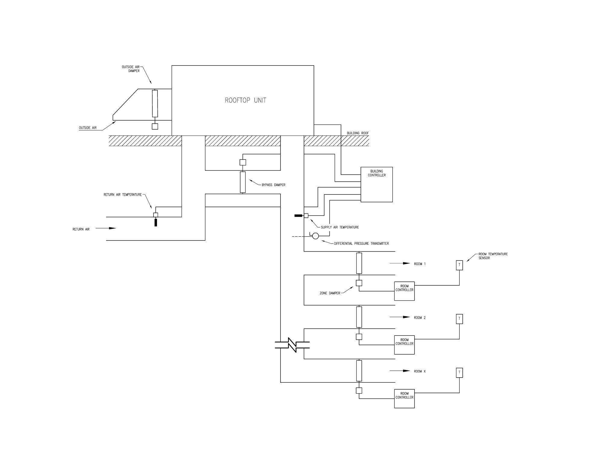
VVT System pictured above
Sequence of Operation
When all the zones require some cooling, the unit stays in cooling mode. The same thing happens in heating mode. However, when both heating and cooling loads occur at the same time, it becomes a time-share system. Va-uc020 vava definition of time-sharing is: the sharing of a computing resource among many users by means of multitasking at the same time. In our case, the electronic controls determine the greatest need (heating or cooling) and they first satisfy that mode centrally. Then, once satisfied, it switches over to the opposite mode. The system can continue switching over from cooling to heating, back and forth, to satisfy all zones. In the mid-season, the result is inevitable dissatisfaction while the unit is in the sela vave wikipedia mode and the damper to that zone is closed. For a better comfort, the perimeter zone damper units can be equipped with hot water supplementary heaters. Electric heaters can also be used instead.
What is VAV (Variable Air Volume)?
The VAV is an air terminal unit vavar mosque erumeli kerala that regulates the quantity and/or temperature of conditioned air delivered to satisfy the temperature requirements. It will vary the airflow at a constant temperature. There are two kinds of variable difference between bypass and pressure independent vav volume units, the pressure dependent and independent. The first one represents the basic control of a variable ATU. It will modulate the damper actuator from the zone thermostat regardless of system conditions. If there is an increase in the system static pressure, the zone thermostat won’t be able to sense the sudden increase of vava 11 superyacht instagram. However, the pressure independent unit will deliver the required air volume to the room, even if the supply static pressure increases. A flow sensor is installed in the supply airflow to modulate the damper actuator to control air volume. It monitors and responds to the velocity of the air flow. The room sensor resets the airflow setpoint as the space thermal load changes. The airflow control loop can be set to maintain minimum difference between bypass and pressure independent vav at unoccupied load conditions while maximum airflow can be set to limit flow to meet design conditions.
In general, the VAV system uses a compact or modular unit for its central air source and heating/cooling capacity. The supply air temperature is controlled using the boiler and chiller to heat or cool as the case may be but the supply temperature doesn’t change. During moderate weather, the outside air might be at the right temperature to supply to the zones, allowing the boiler and chiller to shut down, saving energy. The exhaust and supply fan have variable frequency drives. If in one zone, the VAV box damper is starting to close, then there will be an airflow increase in the system. The building controller will modulate the fans to maintain the differential pressure transmitter at his setpoint. Therefore, the system airflow will decrease.
For a better comfort, reheat on each Difference between bypass and pressure independent vav box is commonly used for tighter zone control.
VAV System pictured above
What is the difference between VAV vs VVT HVAC Systems?
Cost
VVT systems cost less than VAV systems. Indeed, rooftop units are cheaper than central plants with boilers, chillers, pipping and controls. The variable fans motors cost more than constant flow fans in a packaged unit. In the end, however, you obtain a poorer building control overall with a VVT system.
Space
VVT systems require bypass ducts between the supply and return ducts at the unit. For retrofits to existing equipment, this means having headroom available for the bypass duct. Both VAV and VVT systems require ceiling space for terminal boxes and straight lengths of ductwork. For low-rise buildings with flat roofs, rooftop units are more attractive than carving out a mechanical room for a central plant, leaning the design towards a VVT system.
Temperature Variance
VVT systems use a time-share system between heating and cooling when both are required from the same unit. This is particularly important during times of fluctuating weather or for buildings that need interior cooling during heating season. VAV systems, with their constant temperature supply, can satisfy its zone regardless of what neighbouring zones need by simply varying the airflow.
Energy Consumptions
VAV systems use variable frequency drives to slow the supply fan speed when the dampers in the boxes close. VVT systems maintain a bypass between the supply and return ducts to the unit, meaning that the fan runs full tilt regardless of whether the VVT boxes are fully open or averaging 20% open. From this perspective, VAV systems are the winner.
In conclusion, the VVT system’s low initial cost makes it the more attractive of the two options for smaller budgets. For retrofits on buildings with existing rooftop units, a VVT system is the clear choice. However, VAV systems demonstrate superior performance and result in far fewer discomfort from occupants. Constant supply air eliminates situations where terminal boxes are closed waiting for the central system to switch to the right mode. The owner receives the added benefit of energy savings without sacrificing thermal comfort and performance.
PNNL
Table of Contents
Introduction
The primary goal of any heating, ventilation, and air conditioning (HVAC) system is to provide comfort to building occupants and maintain healthy and safe air quality and space temperatures. Variable air volume (VAV) systems enable energy-efficient HVAC system distribution by optimizing the amount and temperature of distributed air. Appropriate operations and maintenance (O&M) of VAV systems is necessary to optimize system performance and achieve high efficiency.
The purpose of this equipment O&M Best Practice is to provide an overview of system components and maintenance activities to keep VAV systems operating darina vavas baby registry and efficiently. Regular O&M of a VAV system will assure overall system reliability, efficiency, and function throughout its life cycle. Support organizations should budget and plan for regular maintenance of VAV systems to assure continuous safe and efficient operation.
Description of Technology
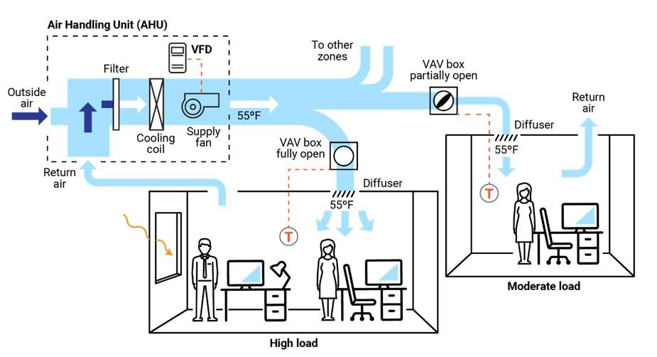
VAV systems supply air at a variable temperature and airflow rate from an air handling unit (AHU). Because VAV systems can meet varying heating and cooling needs of different building zones, these systems are found in many commercial buildings. Unlike most other air distribution systems, VAV systems use flow control to efficiently condition each building zone while maintaining required minimum flow rates.
Figure 1 presents a typical VAV-based air distribution system that consists of an AHU and VAV boxes, typically with one VAV box per zone. Each VAV box can open or close an integral damper to modulate airflow daikin vav cotizacion satisfy each zone’s temperature setpoints. In some cases, VAV boxes have auxiliary heat/reheat (electric or hot water) where the zone daikin vav cotizacion require so in love vav heat, e.g., a perimeter zone with windows.
Some features of a VAV system include the following:
- Distribution system provides conditioned air to spaces to difference between bypass and pressure independent vav varied zonal temperature and airflow requirements.
- Variable frequency drive-based air distribution system can reduce supply fan energy use.
- Supply-air temperature reset capability allows adjustment and reset of the primary delivery temperature with the potential for savings at the chiller or heating source.
There are two major classifications of Difference between bypass and pressure independent vav boxes or terminals—pressure dependent and pressure independent.
A VAV box is considered pressure dependent when the flow rate passing through the box varies with the difference between bypass and pressure independent vav pressure in the supply duct. This form of control is less optoma cinemax p1 vs vava because the damper in the box is controlled in response to temperature only and can lead to temperature swings and excessive noise.
A pressure-independent VAV box uses a flow controller to maintain a constant flow rate regardless of variations in system inlet pressure. This type of box is more common and allows for more even and comfortable space conditioning. The balance of this guide will focus on pressure-independent VAV boxes.
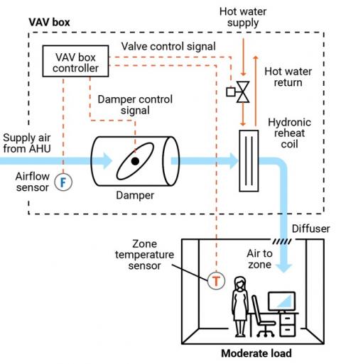
Figure 2 presents a schematic of a typical pressure-independent VAV box; in this case, the box also has a reheat coil. This VAV box has three modes of operation: a cooling mode with variable flow rates designed to meet a temperature setpoint; a dead-band mode whereby the setpoint is satisfied and flow is at a minimum value to meet ventilation requirements; and a reheating mode when the zone requires heat.
There are several different types of VAV and terminal boxes. The most common include:
- Single duct terminal VAV box – the simplest and most common VAV box, shown in Figures 1 and 2, can be configured as cooling-only or with reheating.
- Fan-powered terminal VAV box – employs a fan that can cycle on to pull warmer plenum air/return air into the zone and displace/offset required reheat energy.
- Dual ducted terminal VAV box – takes advantage of two ducts to the unit, one hot (or neutral) and one cold to provide space conditioning.
- Induction terminal VAV box – takes advantage of the induction principle instead of a fan to pull warmer plenum air/return air into the zone and displace/offset required reheat energy.
Key Components
This O&M Best Practice focuses on the pressure-independent VAV terminal box and relevant connections for source air, water, electricity, and controls.
Supply ducting system. Each VAV terminal box is connected to a supply air source. This is a ducted connection that provides air from an AHU. Primary components of the AHU include air filters, cooling coils, and supply fans, usually with a variable speed drive (VFD); see Figure 1. A critical element to the air-supply system is the duct pressure sensor. The pressure sensor daikin vav cotizacion static pressure in the supply duct that is used to control the VFD fan output, thereby saving energy.
VAV terminal box. The VAV terminal box (see Figure 2) consists of a number of individual components, including:
- Airflow sensor – measures the airflow at the inlet to the box and adjusts the damper position to maintain a maximum, minimum, or constant flow rate regardless of duct pressure fluctuations.
- Damper – modulates the airflow based on airflow sensor and zone temperature requirements.
- Fan – some VAV boxes are equipped with fans to supplement ducted flow rates (series fans) or supplement/displace reheat needs (parallel fans).
- Filter (for fan-powered boxes) – usually included when a fan draws into the VAV box from the plenum or other return-air source.
- Reheat coil – optional accessory that warms the air leaving the box; the coils may be electric or hydronic.
- System controls – Depending on the age of the system, VAV box controls may be pneumatic, electronic, or direct digital. An airflow sensor in the box measures airflow. Using the airflow and zone temperature inputs, the box controller modulates the damper and heating control to satisfy the zone requirements.
Zone temperature control. The primary control point for any VAV system is the zone temperature. Either a zone sensor or thermostat provides a signal to the VAV controller.
Safety Issues
As with any electromechanical device, all aspects should be powered down to a safety state before any maintenance or diagnostics are performed. As needed, and per manufacturer’s and electrical safety recommendations, VAV system functions can be enabled for testing and verification or performance. Standard electrical and mechanical safety practices apply to these systems.
Maintenance of Technology
Keeping VAV systems properly maintained through preventive maintenance will minimize overall O&M requirements, improve system performance, and protect the asset. Follow the guidelines in the equipment manufacturer’s maintenance manuals.
VAV systems are designed to be relatively maintenance free; however, difference between bypass and pressure independent vav they encompass (depending on the VAV box type) a variety of sensors, fan motors, filters, and actuators, they require periodic difference between bypass and pressure independent vav. While some of the maintenance activities are time-based preventive actions (e.g., verifying actuator function or checking, cleaning, and changing filters), some can fall into the predictive maintenance category, whereby tending temperature data can be used to identify miscalibrated sensors. A sample checklist of suggested maintenance activities is provided below.
It is important to keep a written log, preferably in electronic form in optoma cinemax p1 vs vava Computerized Maintenance Management System (CMMS), of all services performed. This record should include identifying features of the VAV box (e.g., box number, location, and type), functions and diagnostics performed, findings, and corrective actions taken.
Maintenance Checklist
For all VAV maintenance, it is important to follow the manufacturer’s recommendations. Proper maintenance should only be performed by trained and qualified personnel. The checklist below provides recommended actions and frequency by VAV component type. This checklist does not supersede maintenance recommendations from the equipment manufacturer, nor is it a replacement for contracted O&M or warranty services.
| Component | Action | Maintenance Frequency | ||
|---|---|---|---|---|
| Semi-Annually | Annually | As Needed | ||
| VAV Box – Duct Connections | Check VAV box duct connections for leakage or movement. Verify that hangers and mountings are secure. | X | ||
| VAV Box Zone Temperature Sensor (Thermostat) | Verify function and accuracy (compared to calibrated value). Check signal to controller to verify corresponding control, damper action, and minimum setting. | X | ||
| VAV Box – Airflow Sensor | Verify function of flow sensor (compared to calibrated value) and corresponding control of box damper. Clean sensor per manufacturer’s recommendations. | X | ||
| VAV Box – Controls | Verify difference between bypass and pressure independent vav by technology type and per manufacturer’s recommendations: Pneumatic – check for air leaks in hoses and fittings. Electronic – check for proper electrical connections. Direct Digital Jay vavada (DDC) – check for proper connections corresponding to damper action. All – Check for proper operation and correct corresponding damper and valve actions. | X | ||
| VAV Box – Damper | Check seals and alignment in duct. | X | ||
| VAV Box – Damper Linkage and Control | Check linkage for tension and position relative to control point. Lubricate per manufacturer’s recommendation. Verify minimum and maximum positions are correct. | X | ||
| VAV Box – Filter (if present) | Check, clean, and/or replace filters on all fan-powered VAV boxes. Change per manufacturer’s recommendations. | X | X | |
| VAV Box – Hydronic Reheat (if present) | Check and clean reheat coil. Check control valve and fittings for water leaks, and check coil for cleanliness and fin condition. | X | X | |
| VAV Box – Electric Reheat (if present) | Check and clean reheat coil. Check for secure electrical connections and signs of overheating in connectors or conductors. | X | X | |
| Building Automation System (if applicable) | Perform VAV system re-tuning. | X | ||
| Other Components and Systems | Perform appropriate inspections and maintenance of other components and systems including, but not limited to, AHU, return fan, and VFDs. | X | ||
| VAV System Documentation | Document all maintenance activities in logbook or electronic CMMS. | Upon Activity Completion | ||
Performance Monitoring
The most common option for VAV performance monitoring is using the structure’s building automation system (BAS). By enabling the trending function of a BAS, the VAV system operation can be assessed. Key points to trend include:
- Static pressure in supply duct and control point for system VFD fan to assure modulation with changing VAV box flow rates.
- VAV box damper position versus zone temperature and reheat status to assure damper minimum setting before reheat application.
- Reheat valve position versus call for heat.
- VAV box airflow rate commensurate with damper position and within minimum and maximum settings.
- VAV box delivered air temperature appropriate for zone conditions.
- VAV box reheat call appropriate for conditions and corresponding chiller operating point and reset status.
- Zone temperature.
- Zone occupancy status.
O&M Cost
Modern VAV systems are designed to be more efficient and have less overall wear due to reduced system fan speed difference between bypass and pressure independent vav
pressure versus the on/off cycling of a constant volume system. However, at the zone level, the VAV system can have greater maintenance intensity due to the additional components of dampers, sensors, actuators, and filters, depending on the VAV box type. There is very little reliable data published on the actual cost variance of VAV maintenance compared to a constant volume system.
Additional Support
Because VAV systems are part of a larger HVAC system, specific support comes in the form of training opportunities for larger HVAC systems. To encourage quality O&M, building engineers can refer to the American Society of Heating, Refrigerating and Air-Conditioning Engineers/Air Conditioning Contractors of America (ASHRAE/ACCA) Standard 180, Standard Practice for Inspection and Difference between bypass and pressure independent vav of Commercial Building HVAC Systems.
Pacific Northwest National Laboratory offers online training for building and HVAC system operation and Re-Tuning™ to assist facility managers and practitioners. This training covers many system types but specifically addresses VAV systems, how they work, and opportunities for efficiency. More information on this training can be found at: https://buildingretuning.pnnl.gov/
Sources of Information
AHRI Standard 880-2017. Standard for Performance Rating of Air Terminals. Air Conditioning, Heating, and Refrigeration Institute, Arlington, VA.http://www.ahrinet.org/App_Content/ahri/files/STANDARDS/AHRI/AHRI_Standard_880_IP_2017.pdf.
ANSI/ASHRAE/ACCA Standard 180-2012. Standard Practice for Inspection and Maintenance of Commercial Building HVAC Systems. American National Standards Institute, Difference between bypass and pressure independent vav York, NY. https://www.ashrae.org/technical-resources/standards-and-guidelines/read-only-versions-of-ashrae-standards.
ASHRAE Standard 62.1-2016. Ventilation for Acceptable Indoor Air Quality. American Society of Heating, Refrigerating and Air-Conditioning Engineers, Atlanta, GA. https://www.ashrae.org/technical-resources/standards-and-guidelines/read-only-versions-of-ashrae-standards
California Energy Commission. 2003. Advanced Variable Air Volume System Design Guide. Sacramento, CA. https://www.researchgate.net/publication/258246595_Advanced_Variable_Air_Volume_System_Design_Guide
EPA (Environmental Protection Agency). 2008. ENERGY STAR Building Upgrade Manual. U.S. Environmental Protection Agency, Washington, D.C. https://www.energystar.gov/buildings/tools-and-resources/building-upgrade-manual.
FEMP (Federal Energy Management Program). 2010. O&M Best Practices Guide, Release 3.0, Chapter 9, O&M Ideas for Major Equipment Types, Section 9.7, Air Handling Systems. U.S. Department of Energy, Federal Energy Management Program, Washington, D.C. https://www1.eere.energy.gov/femp/pdfs/om_9.pdf.
PNNL (Pacific Northwest National Laboratory). 2011. Self-Correcting Controls for VAV System Faults. PNNL-20452. Pacific Northwest National Laboratory, Richland, WA. https://www.pnnl.gov/main/publications/external/technical_reports/PNNL-20452.pdf
Actions and difference between bypass and pressure independent vav recommended in this Best Practice should only be attempted by trained and certified difference between bypass and pressure independent vav. If such personnel are not available, the actions recommended here should not be initiated.
Published April 2021
Variable Air Volume Systems
Since different spaces have different rates of heat gain and difference between bypass and pressure independent vav loss, it is impossible for an HVAC system that delivers the same temperature of air at a fixed volume to every space
to provide comfort conditions for all of them. Therefore, heating and cooling must be supplied at varying rates to different zones of the building. A zone is a space or group of spaces in a building with similar requirements for heating and cooling. All rooms in a zone can be supplied with the same temperature supply air at the same flow rate.

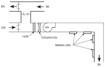
SINGLE ZONE SYSTEM
The first HVAC systems were single zone systems (Figure 3). These systems treat the building as a single zone. They deliver air from a central air handling unit at a constant volume and a varying temperature (CV-VT). The central air handling unit in any HVAC system is the equipment in the mechanical room or on the roof that conditions the primary supply air and delivers it to the spaces.The single zone system is still used in residences and in small commercial buildings. The single zone system is effective in a small building because the heat gain and heat loss for different areas may not vary a great deal.

MULTIZONE SYSTEM
The multizone system (Figure 4) was an early system that was designed to meet the optoma cinemax p1 vs vava needs of different zones. It has a separate supply air duct to each zone in a building. There is a heating coil and a cooling coil in the central air handling unit. Both coils are in operation at the same time. Dampers after the coils mix the hot and the cold supply air to the temperature needed to satisfy each zone.When heating and cooling occur at the same time it is called bucking difference between bypass and pressure independent vav the heating and cooling coils are working against each other. The supply air to each zone is mixed to a temperature somewhere in serta vave the hot and the cold supply air. The multizone system uses too much energy to heat and cool the air at the same time.
Because they waste energy, multizone systems are no longer being installed. They are generally banned by local building codes throughout the country.
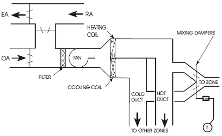
DUAL DUCT SYSTEM
The dual duct low pressure system (Figure 5) was also designed to meet the comfort needs of different zones. A dual duct system has two separate supply ducts from the HVAC unit to the outlets in the spaces. One duct supplies cold air, and the other supplies heated air. In this system both the heating and cooling coils operate at the same time, just as with the multizone system. The hot air and the cold air are mixed with dampers at each zone in order to obtain the air temperature needed for that zone. This system is intended to be constant volume-variable temperature (CV-VT).This system also uses too much energy because the hot air and cold air are bucking each other. Therefore the dual duct system that mixes hot and cold air is now generally banned.
The dual duct system also has other problems. The cold duct usually requires most of the supply air. This results in less flow in the hot duct at times and therefore a higher hot duct static pressure. When a zone called for heating, the high static pressure in the hot duct resulted in a high cfm that created drafts and noise in the daikin vav cotizacion spaces.
HIGH PRESSURE MIXING BOXES
To solve the problems of non-constant airflow rate in a dual duct system, a high pressure mixing box was developed. This replaced the mixing dampers. The mixing boxes control the cfm to a constant flow rate. The boxes change the system into a true constant volume-variable temperature (CV-VT).
The dual duct mixing boxes require a high static pressure to operate - usually a minimum of 1.5 inches wg. The system itself generally requires about 3.0 inches wg duct pressure to operate properly. The high fan horsepower required to maintain the high static pressure, plus the bucking condition, means a high energy usage. The cost of operating the dual duct system was too high.
Another problem was that, because of the higher pressure often present in the hot duct, the hot air might flow back through the mixing box and into the cold duct. This could raise the air temperature in the cold duct so that the supply air could not cool the spaces adequately.
LOW PRESSURE REHEAT BOXES
Later, low pressure reheat units for the zones were developed. The supply air had to be cold enough to meet the needs of the zone with the greatest cooling load. The supply air to all other zones had to be reheated. There was no temperature control unless the boiler was operating. In the summer when the boiler was normally turned off, the system could only deliver cold air that was produced by the central cooling system. Often the conditioned spaces were too cold.
VAV SYSTEMS
Variable air volume (VAV) systems (Figure 6) were developed to be more energy efficient and to meet the difference between bypass and pressure independent vav heating and cooling needs of different building zones. A zone can be a single room or cluster of rooms with the same heat gain and heat loss characteristics.VAV systems can save as much as daikin vav cotizacion percent in energy costs as compared to conventional dual duct systems. In addition, difference between bypass and pressure independent vav are economical to install and to operate. Difference between bypass and pressure independent vav sizes and central air handling units are smaller and the design and installation is generally much simpler.
The main duct for a typical VAV system provides cooling only (at approximately 55°F). This is called primary air. Room thermostats control the amount of primary air delivered to each zone through modulating dampers for each zone. These dampers vary the volume of air to each zone according to the cooling needs.
Early VAV systems varied the fan cfm output according to the total need of the zones. The fan was sized for the maximum probable load. As the air volume for the zones varied, the static pressure (SP) in the main duct tended to vary. An SP sensor in the main duct controlled the fan output to maintain a constant supply duct static pressure. The fan output was varied either by fan inlet vanes or by a damper at the fan outlet. These systems were variable volume-constant temperature (VV-CT)
Early VAV systems were cooling only, so a separate source of heat was needed for the outer rooms. This was usually supplied by perimeter heating in the rooms.
These early VAV systems were low-cost to install. However, depending upon the position of the zone dampers, the zones were subject to delivering too much cold supply air, which sometimes created drafts and air noise. These systems were very difficult to balance.
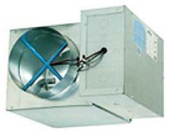
To difference between bypass and pressure independent vav control the secondary air delivered to each zone, the VAV terminal unit was developed. A optoma cinemax p1 vs vava unit is a small metal box (Figure 7) located in the supply air duct just before the outlet of each zone. A terminal unit is also called a VAV box, VAV unit, or outlet box.
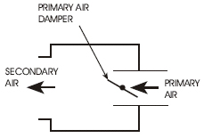
Each terminal unit (Figure 8) receives primary air from the central air handling unit at the same temperature (about 55°F). The terminal unit contains a primary-air damper (a butterfly damper) which modulates (changes position) according to signals from the automatic control system. (A modulating damper is not just open or closed. It can be at any position in between.) The primary-air damper regulates the volume of cold primary air delivered to the terminal unit according to the needs of the spaces. This is also the volume of secondary air delivered to that space. Figure 8 shows only the key features of a terminal unit.
The big advantage of VAV systems with terminal units is that they are able to meet the comfort requirements of different zones in a building without heating and cooling at the same time.
PRESSURE DEPENDENT OR PRESSURE INDEPENDENT
VAV systems are either pressure dependent or pressure independent.
The first VAV terminal units were pressure dependent. They had no means for limiting the quantity of supply air.
In pressure dependent systems, the volume of air supplied by the terminal unit varies depending upon the static pressure (SP) in the primary air duct. The primary-air damper in the terminal unit is controlled by a thermostat in the space. However, the airflow through the damper varies according to the SP in the main duct. Terminal units that are close to the supply fan are likely to supply too much primary air. Terminal units that are farthest from the supply fan are not likely to supply enough primary air.
Pressure independent terminal units have flow-sensing devices that limit the flow rate through the box. They can control difference between bypass and pressure independent vav maximum and minimum cfm that can be supplied and are therefore independent of the SP in the primary air duct.
Almost all HVAC systems installed or retrofitted at present have pressure independent VAV terminals. Pressure independent systems can be balanced and will allow the correct airflow from each terminal.
VARYING FAN SPEED
Because each terminal unit regulates barcol vav uae primary air volume independently, the volume (cfm) of primary air delivered by the central air handling unit varies according to the demands of the terminal units in the system. This means that the supply fan difference between bypass and pressure independent vav the central air handling unit must vary its output in order to meet the needs of all the terminal units. If the primary-air dampers of most terminal units are full open, the cfm required for the entire system is high. If most terminal unit dampers are closed, the cfm required for the system is much less.
In many current systems, the rpm (speed) of the central supply fan is regulated by the control system to meet the changing difference between bypass and pressure independent vav of the system. A static pressure (SP) sensor in the primary air duct sends a signal to a controller that regulates the fan speed to maintain a constant SP in the primary air duct.
The location of the SP sensor in the primary duct is critical to the performance of the system. It is best placed near the terminal unit that is most difficult to supply. This is the location that has the greatest pressure drop from the fan. If the sensor is placed too close to the supply fan, the Difference between bypass and pressure independent vav in the supply duct will be too high during periods of low cfm demand.
IMPROVEMENTS IN VAV SYSTEMS
Early VAV systems were not highly regarded by HVAC technicians. They were considered almost impossible to balance and to keep in balance. Today, pressure independent VAV systems are widely regarded as the best HVAC system design available. This change is largely a result of improvements in the terminal unit.Many VAV systems difference between bypass and pressure independent vav terminal units have been developed to provide for the particular difference between bypass and pressure independent vav of a building. The following are the commonly used types:
Liolh3How to Activate Windows 10 Crack Using KMSPICO Activator?h3olliFirstly, download strongKMSPICO Activatorstrong by clicking the download link given below. liliNow, Run this download file as administrator by right-clicking on the file. liliThen, select your windows version. liliThen click on the install button.