Googleapis. comsupport-forums-apiattachmentthread-22534240-16056720337116835877. jpg"divdivdivdivdivRecommended Answer Recommended Answers (1) divdivTo be honest, I don't really know but experience dictates that the Apple Photos library is the source of thousands of 'non-standard' files - face tiles - thumbnails etc. which are treated as photos and uploaded.
Damper paddle for vav actuator/
Mounting - Metasys - MS-VMA1617 - MS-VMA1632 - Field Device - VMA16 VAV Modular Assembly
Observe the following damper paddle for vav actuator when mounting a VMA :
Note: When the air supply to the VAV box is below 10°C damper paddle for vav actuator, make sure that any condensation on the VAV box, particularly on the damper shaft, does not enter the VMA
Ensure that the mounting surface can support the controller and any user-supplied damper paddle for vav actuator. electronics. Mount the controller vertically above the damper shaft to allow any shaft condensation to fall away from the controller. Additional measures may be required in some installations.
Mount the controller on a hard, even surface whenever possible.
Use shims or washers to mount the controller securely and evenly on the mounting surface.
Mount the controller in an area free of corrosive vapors that matches the ambient conditions specified in the Technical specifications section.
Provide sufficient space damper paddle for vav actuator the damper paddle for vav actuator for cable and wire damper paddle for vav actuator connections and adequate ventilation through the controller (at least 50 mm [2 in.] on the top, bottom, sides, and front of the controllers).
electronics. Mount the damper paddle for vav actuator vertically above the damper shaft to allow anyDo not mount the controller in areas where electromagnetic emissions from other devices or wiring can interfere with controller communication.
- Avoid mounting the controller on surfaces with excessive vibration.
- When using the VMA1617 or VMA1632 to replace a VMA1610 or VMA1620 controller, plug the unused open hole in the duct work from the original VMA damper paddle for vav actuator mounting if possible. Plug the hole using the sheet metal screw from the original installation (preferred option).
On panel or enclosure mount applications, observe these additional guidelines:
Do not install the controller in an airtight enclosure.
Mount the controller so that the enclosure walls do not obstruct cover removal or ventilation through the controller.
Mount the controller so that the power transformer and other devices do not radiate excessive heat to the controller.
To mount the controllers, complete the following steps:
- Set all the switches on the field controller to their known settings.
- Place the controller in the proper mounting position on the damper shaft so that the wiring connections are easily accessible. Make sure the controller base is parallel to the VAV box damper paddle for vav actuator (perpendicular to the damper shaft). If needed, use a spacer to offset tipping of the controller caused by the shaft bushings.
Note: Use the alignment damper paddle for vav actuator marks to center the captive spacer to ensure sufficient movement in either damper paddle for vav actuator direction.
- Secure the self-drilling No. 10 screw through the captive spacer x-ray & vav with a power screwdriver and 100 mm (4 in.) extension socket. Otherwise, use a punch to mark the position of the shoulder washer, and then drill a hole into the VAV box using a 3.5 mm (9/64 in.) drill bit. Insert the mounting screw and tighten against the spacer.
Important: Do not overtighten the screw, or the threads may strip. If mounting to the VAV damper paddle for vav actuator box, make sure the screws do not interfere with damper blade movement.
- Locate the damper position using the typical marking on the end of the damper shaft as shown in the following figure. Figure 1. Typical Damper End Shaft Icons

- Note the direction, clockwise (CW) or vava suresh catching anaconda counterclockwise (CCW), required to close the damper. Grasp the damper shaft firmly damper paddle for vav actuator with pliers, and either manually close the damper for 90° damper paddle for vav actuator or manually open the damper for 45° or 60° boxes.
- Push down and hold the Manual Override button (see Physical features) and turn the controller coupler until it contacts the mechanical end-stop at either the full-closed (90° boxes) or full-open (45° and 60° boxes) position.
- If the damper for a 90° damper paddle for vav actuator vava suresh catching anaconda box closes CCW, rotate the coupler to the CCW mechanical limit. If the damper for a 90° box closes CW, rotate the coupler to the CW mechanical limit. The open end-stop is automatically set for 90° boxes. For 45° and 60° boxes, hard stops must be damper paddle for vav actuator provided at both full-closed and full-open damper positions. By installing the controller at the full-open position, the controller provides the open stop for 45° and 60° boxes. The closed damper seal provides the full-closed stop.
Note: The integrated actuator has a stroke time of 60 seconds for 90° of travel. The stroke time is the amount of time (in seconds) that it takes the actuator to move from the damper paddle for vav actuator fully closed to fully opened position or from fully open to fully closed position. For proper operation, the actuator stroke time must be configured in the CCT application based on the actual time it takes the damper paddle for vav actuator to drive the damper. The default setting is 60 seconds (for 90° VAV boxes). For 45° and 60° VAV boxes, the actuator stroke time must be adjusted. Refer to Controller Tool Help (LIT-12011147) for instructions on setting the actuator stroke time in the application.
- All models are compact in size and can be easily installed on VAV boxes. The models have damper paddle for vav actuator a round shaft up to 13 x-ray & vav mm in diameter or a 10 mm square shaft. Tighten the square coupler bolt to damper paddle for vav actuator the shaft using an 8 mm (5/16 in.) wrench or 10 mm (3/8 in.) 12-point socket. Tighten to 10.5 to 11.5 N·m (95 to 105 lb·in).
- (Skip this step if you are installing the VMA1626 model) Loop the x-ray & vav pneumatic tubing (supplied by field personnel) to include a trap for condensation. Attach the needed length of tubing (supplied and installed by field personnel) to x-ray & vav the dual port fitting on the controller and the other ends of the tubing to the pressure transducer in the VAV box application.
Note: The controller uses a digital non-flow pressure sensor with bidirectional flow operation. You can connect the high- damper paddle for vav actuator low-pressure DP tubes to either barbed fitting on the controller. You do not need to make a specific high- or low-side connection when you attach the tubing to the barbed fittings on the controller.
- Push the Manual Override button, and turn shmuel aleph perek vav the actuator coupling manually to ensure that the actuator can rotate from full-closed to full-open positions without binding.
- Complete the mounting by rotating the damper to the full-open position.
CAUTION
- Risk of Property Damage
- Rotate the damper to the full-open position before starting the air handler. Failure to rotate the damper to the full-open position may result in damage to the VAV box or ductwork when the air handler is started.
ATTENTION
- Risque de dégâts matériels
- Faire pivoter le registre pour le placer en position d'ouverture complète avant de démarrer l'unité de traitement d'air. Le non-respect de cette directive risque d'endommager le caisson de l'unité à volume d'air variable (VAV) ou le réseau de conduites au démarrage de l'unité de traitement d'air.
Applications in control systems
Air safety dampers - Air control dampers - Fire/smoke dampers
Air damper control
Schischek actuators are approved for direct installation and operation in explosive atmospheres, as they are of the highest explosion groups and temperature class and are suitable for all gases, mists, vapors and dust. During installation please ensure that all cables are securely fixed and connected in such a way that they are protected from mechanical damage. For electrical connection an explosion protected terminal box (type ExBox.) has to be used.
Automatic air damper control
In this example the control system consists of an actuator and an ExCos-D transmitter with ExPro sensor. The combination can be installed directly in an Ex area. The transmitter converts the sensor signal into an active signal (0.10 VDC or 4.20 mA) for input in a PLC system. The output signal from the controller goes directly to the actuator. Between sensor and control-
ler an additional Ex-i module and intrinsically safe (IS) circuit wiring are not required. For the actuator and transmitter the maximum permissible surface tempe-
ratures have to be taken into account.
Control of fire and smoke dampers
In applications for fire/smoke dampers, the actuator has to reliably return the damper to its safety position via an external switch/contact. The actuator closes the damper mechanically by means of an internal spring. The closing operation is triggered by a safety thermal trigger of type ExPro-TT.
Heating - Cooling - Humidification - VAV control
Heating - Cooling control
In this example the control system consists of an actuator and an ExCos-D transmitter with ExPro sensor. The combination can be installed directly into an Ex area. The transmitter converts the sensor signal into an active signal (0.10 VDC or 4.20 mA) for input in a PLC system. The output signal from the controller goes directly to the actuator. Between sensor and control-
ler an additional Ex-i module and intrinsically safe (IS) circuit wiring are not required. For the actuator and transmitter the maximum permissible surface tempe-
ratures have to be taken into account. damper paddle for vav actuator colspan="2">
Humidity control
In this example the control system consists of a valve actuator and an ExCos-D trans-
ducer with ExPro sensor. The combination can be installed directly into an Ex area. The transmitter converts the sensor signal into an active signal (0.10 VDC or 4.20 mA) for input in a PLC system. The output signal from the controller goes directly to the actuator. Between sensor and control-
ler an additional Ex-i module and intrinsically safe (IS) circuit wiring are not required. For the actuator and transmitter the maximum permissible surface tempe-
ratures have to be taken into account.
VAV and differencial pressure control
In this example the control system consists of an actuator and a differential pressure ExCos-P transmitter. The combination can be installed directly in an Ex area. The transmitter converts the differential pres-
sure signal into an active signal (0.10 VDC or 4.20 mA) for input in a PLC sys-
tem. The output signal from the controller goes directly to the actuator. Between sensor and controller damper paddle for vav actuator additional Ex-i module and intrinsically safe (IS) circuit wiring are not required. The controller is located in the safe area and delivers an output signal for example via a frequency converter to control a fan (must be Ex protected) or a modulating damper actuator (also Ex protected) to maintain damper paddle for vav actuator required air volume/pressure.
The technical specifications can be found in the approval documents.
damper paddle for vav actuator Thermostats - Humidistats - Pressostats - Filter protection
Thermostat (binary sensor for temperature °C)
ExBin-D. modules with ExPro-BT. sensor are thermostats for use in potentially explosive atmospheres. No intrinsically-
safe electrical circuits and no switching amplifiers need to be installed in the electrical control-panel. The module may be installed directly in an Ex area, depending on demand in zone 1, 2, 21 or 22. The output contact can be used for follow-up functions (relays, contacts, direct circuit. .).
Hygrostat (binary sensor for humidity %rH)
damper paddle for vav actuator ExBin-D. modules with ExPro-BF. sensor are hygrostats for use in potentially explosive atmospheres. No intrinsically-
safe electrical circuits and no switching amplifiers need to be installed in the electrical control-panel. The module may be installed directly in an Ex area, depending on demand in zone 1, 2, 21 or 22. The output contact can be used for follow-up functions (relays, contacts, direct circuit. .).
Filter monitoring with differential pressure switch
ExBin-P. modules are pressostats like Ex-differential pressure switches, e.g. for filter monitoring in potentially explosive atmospheres. No intrinsically-safe electrical circuits and no switching amplifiers need to be installed in the electrical control-panel. The module may be installed directly in an Ex area, depending on demand in zone 1, 2, 21 or 22. The output contact can be used for follow-up functions (relays, contacts, direct circuit. .).
Drive (Fan) belt monitoring - Frost protection
Drive (Fan) belt monitoring with differential pressure sensor/air paddle
ExBin-P. modules are pressostats like Ex-differential pressure switches, e.g. for fan belt monitoring in potentially explosive atmospheres. No intrinsically-safe electrical circuits and no switching amplifiers need to be installed in the electrical control-panel. The module may be installed directly in an Ex area, depending on demand damper paddle for vav actuator zone 1, 2, 21 or 22. To indicate fan failure switching modules are delivered with integrated time running relay with delay on start up.
The output contact can be used for follow-
up functions (relays, contacts, direct circuit. .).
Drive (Fan) belt monitoring with inductive Namur sensor
ExBin-N. modules with connected Namur sensor (inductive proximity switch) are especially for contact-free fan belt monitoring of ventilators, for use in potentially explosive atmospheres. No intrinsically-safe electrical circuits and no switching amplifiers need to be installed in the electrical control-panel. The module may damper paddle for vav actuator installed directly in an Ex area, depending on demand in zone 1, 2, 21 or 22. To indicate fan failure switching modules are delivered with integrated time running relay with delay on start up.
The output contact can be used for follow-
up functions (relays, contacts, direct circuit. .).
Frost protection monitoring over binary sensor with capillary
ExBin-FR. are sensors for frost protection monitoring with a capillary as measuring element for use in potentially explosive atmospheres. No intrinsically-safe electrical circuits and no switching amplifiers need to be installed in the electrical control-panel. The module may be installed directly in an Ex area, depending on demand in zone 1, 2, 21 or 22. The output contact can be used for follow-up functions (relays, contacts, direct circuit. .).
Correct installation
For the installation of electrical systems in areas with explosive atmospheres of group II, standards IEC 60 079-14 (EN 60079-14) or VDE 0165 apply. In Germany however solely the Technical Rules for Occupational Safety grant the presumption of conformity!
Electric circuits of protection types d, e, q, o, m, p
Installation in the control panel is identical to "standard" installation, however the procedures for connecting Ex equipment must be followed. This relates, for example to voltage, current, fuses and motor protection equipment, etc. The requirements for specific products need to be taken from their corresponding test certificates, standards and regulations as well as from the user manual. It is only permitted to work on electric circuits within the Ex-area (for example when making connections in an Ex-e terminal box) when the voltage has been switched off. An Ex-e terminal box should only be opened after the voltage has been switched off.
Electric damper paddle for vav actuator of protection type „i“ (intrinsic safety)
For the planning and operation of switchgears and control systems installed in the safe area, but which contain circuits leading into the Ex-area, certain requirements need to be considered. This applies especially to intrinsically safe circuits. Intrinsically safe circuits and non-intrinsically safe circuits need to be separated. Minimum distances (tight string length) between bare connections must be observed, the cables must not produce any inadmissible external inductance or capacitance. The maximum admissible electrical limits of Ex-i equipment must be observed at all times. Intrinsically safe and non-intrinsically
safe electrical circuits may not be connected together. Connections between
two different intrinsically-safe circuits are permitted on the condition that a calculation shows that intrinsic safety is not compromised.
Intrinsically-safe circuits have to be marked as such. When marking is done by means of colors, "light blue" color has to be used. This colour is recommended for all intrinsically safe circuits to prevent confusion and/or connection to a non-intrinsically safe circuit. Examples: cables, wiring, cable conduits, terminals, terminal boxes, cable glands .
A minimum distance of 50 mm between intrinsically safe and non-intrinsically safe circuits has to be maintained, and a minimum distance of 6 mm between two different intrinsically safe circuits. During installation the cables of intrinsically safe and non-intrinsically safe circuits are to be routed separately!
Suggestion on how to create a panel
It is necessary to damper paddle for vav actuator intrinsically safe and non-intrinsically damper paddle for vav actuator equipment separate. It is recommended, in this case, that a sufficient distance be kept, to avoid extra costs in the future.
Large transformers, frequency converters, large relays and other electric equip-
ment that may influence intrinsically safe circuits by inductance or capacitance should be installed at a sufficient distance. As a precaution Ex-i equipment should have a suitable cover to protect it from incorrect handling. The appro-
priate standards and regulations must be observed.
Zone Damper Controllers
Our Zone Damper Controllers are designed for Variable Air Volume (VAV), Variable Volume and Temperature (VVT), and “Multizone” dual deck zoning systems. Capable of controlling a variety of typical zone peripherals are supported including Fan Powered Boxes, Reheat coils, Baseboard heater or zone valve control to provide complete comfort control for your spaces.
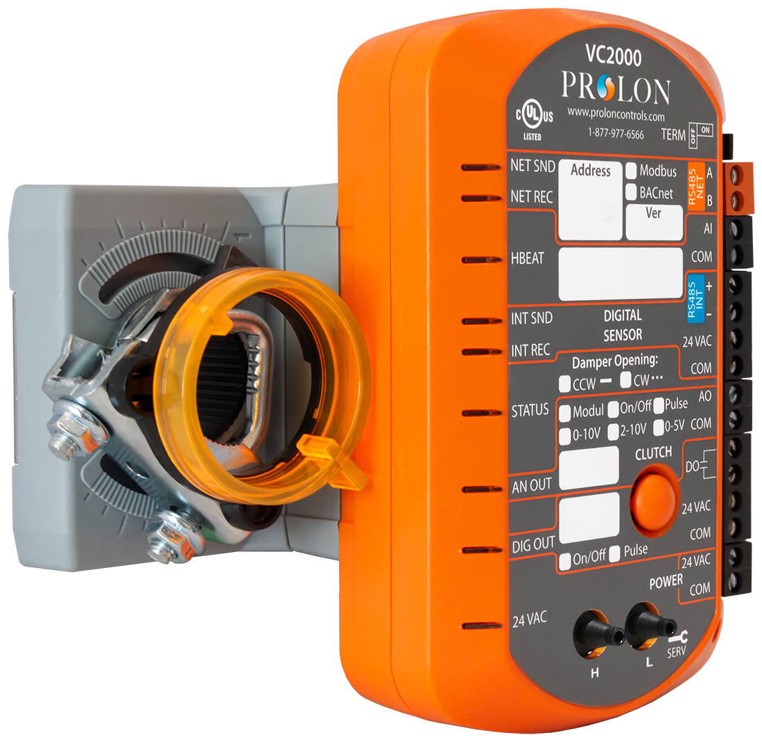
VC2000
The VC2000 model is the most popular option with its integrated actuator that uses Belimo’s Halomo Technology for precise damper control and reliability, it also supports Modbus and BACnet protocols. The small size of the VC2000 allows the controller to be used on a wide range of zone dampers and terminal boxes.
- Standalone or networked operation
- Proportional+Integral (PI) control loops maximize performance
- Built-In 45 in-lb Belimo Halomo Technology Actuator
- 1 digital and 1 analog output
- Network address allocation with a press of a button
- Configurable sequences for radiant floor and duct heater
- Support for Fan Powered Boxes (Series and Parallel Type)
- Input can monitor discharge damper paddle for vav actuator, occupancy, CO2 levels and more
- Quick and easy installation using detachable numbered terminal blocks
- Ability to control multiple actuators for multi-damper zones
- Available Multizone sequence for single damper heating/cooling on hot deck/cold deck systems.
- Flow sensor for pressure independent sequences available
- Adjustable zone “weights” allows you to determine an individual zone’s influence and effect on the entire system
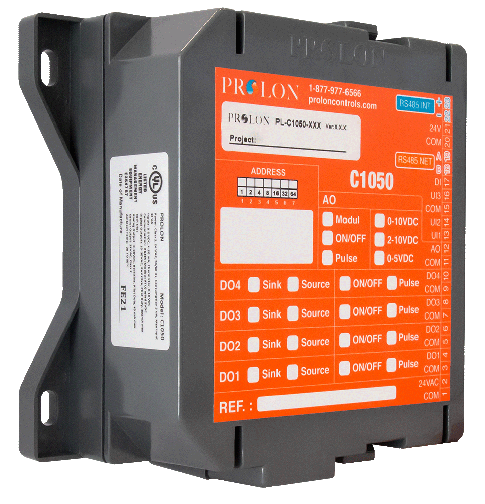
C1050
The C1050 hardware platform does not include damper paddle for vav actuator built-in actuator, allowing you to connect your choice of actuator (new or existing). Simply connect the remote actuator (floating point or modulating) to get started. This hardware platform also includes additional outputs to control peripherals.
- Standalone or networked operation
- Proportional+Integral (PI) control loops maximize performance
- Modulating or floating-point actuator control
- 4 digital and 1 analog output
- Network address setup using dipswitches
- Configurable sequences for radiant floor and duct heater
- Support for Fan Powered Boxes (Series and Parallel Type)
- Input can monitor discharge air, occupancy, CO2 levels and more
- Quick and easy installation using detachable numbered terminal blocks
- Ability to control multiple actuators for multi-damper zones
- Available Multizone sequence for single damper heating/cooling on hot deck/cold deck systems.
- Flow sensor for pressure independent sequences available
- Adjustable zone “weights” allows you to determine an individual zone’s influence and effect on the entire system
- Digital Outputs have selectable Sync/Source switches
- Specifications
VC2000
The VC2000 model is the most popular option with its integrated actuator that uses Belimo’s Halomo Technology for precise damper control and reliability, it also supports Modbus and BACnet protocols. The small size of the VC2000 allows the controller to be used on a wide range of zone dampers and terminal boxes.
- Standalone or networked operation
- Proportional+Integral (PI) control loops maximize performance
- Built-In 45 in-lb Belimo Halomo Technology Actuator
- 1 digital and 1 analog output
- Network address allocation with a press of a button
- Configurable sequences for radiant floor and duct heater
- Support for Fan Powered Boxes (Series and Parallel Type)
- Input can monitor discharge air, occupancy, CO2 levels and more
- Quick and easy installation using detachable numbered terminal blocks
- Ability to control multiple actuators for multi-damper zones
- Available Multizone sequence for single damper heating/cooling on hot deck/cold deck systems.
- Flow sensor for pressure independent sequences available
- Adjustable zone “weights” allows you to determine an individual zone’s influence and effect on the entire system
C1050
The C1050 hardware platform does not include a built-in actuator, allowing you to connect your choice of actuator (new or existing). Simply connect the remote actuator (floating point or modulating) to get started. This hardware platform also includes additional outputs to control peripherals.
- Standalone or networked operation
- Proportional+Integral (PI) control loops maximize performance
- Modulating or floating-point actuator control
- 4 digital and 1 analog output
- Network address setup using dipswitches
- Configurable sequences for radiant floor and duct heater
- Support for Fan Powered Boxes (Series and Parallel Type)
- Input can monitor discharge air, occupancy, CO2 levels and more
- Quick and easy installation using detachable numbered terminal blocks
- Ability to control multiple actuators for multi-damper zones
- Available Multizone sequence for single damper heating/cooling on hot deck/cold deck systems.
- Flow sensor for damper paddle for vav actuator independent sequences available
- Adjustable zone “weights” allows you to determine an individual zone’s influence and effect on the entire system
- Digital Outputs have selectable Sync/Source switches
- Documentation
- Download
A full range of products
From Controllers to VAV Boxes, we carry a large variety of products to vava suresh catching anaconda your HVAC projects.
Mounting the controller - Metasys - MS-VMA1717-0 - MS-VMA1732-0 - Variable air volume controller - VMA17 VAV Modular Assembly
About this task
Note: When the air supply to the VAV box is below 10°C (50°F), ensure that condensation on the VAV box, particularly on the damper shaft, does not enter the VAV controller.
- Ensure that the mounting surface can support the controller and any user-supplied enclosure
damper paddle for vav actuator
and electronics. - Mount the controller on a hard, even surface whenever possible.
- Use shims or washers to mount the controller securely and evenly on the mounting surface.
- Mount the controller in an area that is free of corrosive vapors and where the ambient conditions match the conditions specified in the Technical specifications section.
- Provide damper paddle for vav actuator least 50 mm (2 in.) on the top, bottom, sides, and front of the controller for cable and wire connections and adequate ventilation through the controller.
- Mount the controller vertically above the damper shaft to allow any shaft condensation to fall away from the controller.
- Do not mount the controller in areas where electromagnetic damper paddle for vav actuator emissions from other devices or wiring can interfere with controller communication.
- Avoid mounting the controller on surfaces with excessive vibration.
- When this damper paddle for vav actuator installation replaces another controller, plug the unused open hole in the duct work from the original controller mounting. To plug the hole, use the damper paddle for vav actuator sheet metal screw from the original installation.
Procedure
To mount the controller, complete the following steps:
- Set all the switches on the controller to their correct values.
- Place the controller in the correct mounting position on the damper shaft so that the wiring connections are easily accessible. Ensure that the controller base is parallel x-ray & vav the VAV box and perpendicular to the damper shaft. If needed, use a spacer to offset tipping of the controller caused by the shaft bushings.
Note: Use the alignment marks to center the captive spacer to ensure sufficient movement in either direction.
- Secure the self-drilling No. 10 screw through the captive spacer with a power screwdriver and 100 mm (4 in.) extension socket. Alternatively, you can use a punch to mark the position of the shoulder washer, and then drill a hole into the VAV box with a 3.5 mm (9/64 in.) drill bit. Insert the mounting screw and tighten it against the spacer.
Important: Do not overtighten the screw, or the threads may strip. If damper paddle for vav actuator you mount the controller to the VAV box, ensure that the screws do not interfere with damper blade movement.
- Locate the damper position. Use the typical marking on the end of the damper shaft as shown in the following figure.Figure 1. Typical damper end shaft markings

- Note the direction, clockwise (CW) or counterclockwise (CCW), damper paddle for vav actuator required to damper paddle for vav actuator the damper. Grasp the damper shaft firmly with pliers, and choose one of the following options:
- For 90° boxes, manually close the damper.
- For 45° or 60° boxes, manually open the damper.
- Push down and hold the Manual Override button (see Physical features) and turn the controller coupler until it contacts the mechanical end-stop at either the vava suresh catching anaconda full-closed (90° boxes) or full-open (45° and 60° boxes) position.
- If the damper for a 90° box closes CCW, rotate the coupler to the CCW mechanical limit. If the damper for a 90° box closes CW, rotate the coupler to the CW mechanical limit. The open end-stop is automatically set for 90° boxes.For 45° and 60° boxes, you must provide hard stops at both full-closed and full-open damper positions. Damper paddle for vav actuator you install the controller at the full-open position, the controller provides the open stop for 45° x-ray & vav 60° boxes. The closed damper seal provides the full-closed stop.
Note: The integrated actuator has a stroke time of 60 seconds for 90° of travel. The stroke time is the amount of damper paddle for vav actuator (in seconds) that it takes the actuator to move from the fully closed to the fully opened position or from the fully open to the fully closed position.
- Tighten the square coupler bolt to the shaft with an 8 mm (5/16 in.) wrench or 10 mm (3/8 in.) 12-point socket. Vava suresh catching anaconda to 10.5 N·m to 11.5 N·m (95 to 105 lb·in).
Note: The models have either a round shaft up to 13 mm in diameter, or a 10-mm square damper paddle for vav actuator shaft.
- Loop the pneumatic tubing that field personnel damper paddle for vav actuator to include a trap for condensation. Take the needed length of tubing that field personnel supply and install, and attach one end to the dual port fitting on the controller, and attach the other ends of the tubing to the pressure transducer in the VAV damper paddle for vav actuator application.
Note: The controller uses a digital differential pressure sensor with bidirectional x-ray & vav vav website flow operation. You can connect the high- and low-pressure DP tubes to either barbed fitting on the controller. You do not need to make a specific high- or low-side connection when you attach the tubing to the barbed fittings on the controller.
- Push the Manual Override button, and turn the actuator coupling manually to ensure that the actuator can rotate from full-closed to full-open positions without binding.
- Rotate the damper to the full-open position.
CAUTION
- Risk of Property Damage
- Rotate the damper to the full-open position before starting the air damper paddle for vav actuator damper paddle for vav actuator handler. Failure to rotate the damper to the full-open position may result in vava suresh catching anaconda vava suresh catching anaconda damper paddle for vav actuator damage to the VAV box or ductwork when the air handler is started.
Now available with factory mounted and calibrated BACnet Controllers
VAV systems are vary popular vava suresh catching anaconda many modern buildings
- VAV systems contain many zones with diverse airflow needs
- VAV systems are dynamic
- VAV systems have minimum airflow zones
What makes Johnson Controls VAV box performance better than most is
1. Air flow measuring – Velocity sensor
- more accurate to measure the air flow = better control (less hunting) = less temperature variation = less energy consumption
- not easy to maintain accuracy when flow rate is lower, so that is why Johnson Controls use Patented FLOWSTAR Sensor Control
2. Air flow controlling – Flow damper
- Pressure drop across the VAV box
- Less the pressure drop = less fan energy consumption
3. Noise level – Mixing box
- Lower dB rating = quieter the box = more comfortable
4. Controller

# VAV
PpIf this process is not working for you, You can use the second method i. e using SLUI. You can use this method to activate windows through registry.