This upgrade scheme was discontinued as of version 10. sup91;293;sup WinZip is available in standard and professional versions.
However, the shell in Windows ME and later versions of Microsoft Windows has the ability to open and create. zip files (titled "compressed folders"), which reduces the need for extra compression software.
Air terminal unit vav/
A Simple & Cost-Effective Device for Zone Airflow Control
The control of air distribution in modern buildings is typically accomplished by the use of air terminal units. A terminal unit is a device that is used to regulate the volume of conditioned primary air from the central air handler to the occupied space. Watch this video vav box k factor calculation learn more!
Terminal units are available in several different types, each designed to suit specific applications.The terminal unit types listed below are the most common configurations used in the HVAC industry.
Single Duct
The single duct is the simplest and most cost-effective type of terminal unit, and is commonly referred to as a VAV box. Typical single duct construction includes:
- a round inlet where the flow sensor and damper are mounted
- a rectangular casing that incorporates a liner with acoustic and/or thermal benefits.
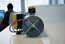
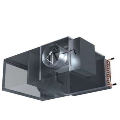
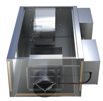
Fan Powered
A fan powered terminal unit, commonly referred to as a fan powered box, is an air terminal unit which contains both a primary air inlet, as well as a local motor and blower assembly. Fan powered terminals generally come in either a parallel or series arrangement, determined by the location of the fan in the vave global bergerak dalam usaha apa. A series fan powered terminal air terminal unit vav with a sensible cooling coil is available for zone control in a dedicated outdoor air system (DOAS).
Dual Duct
A non-mixing dual duct terminal is essentially two single ducts fastened together with one common discharge opening. The inlets are connected to two of the following: cold air, warm air, or fresh air. A mixing dual duct terminal unit is similar to the non-mixing type, but has an integral mixing section between the two supply valves and the discharge duct connection. Different levels of mixing performance are available.

To learn more about terminal units, visit our Terminals site or contact an Application Engineer at [email protected].
What You Need to Know About Air Terminal Units
If you’ve ever walked into a cool building after being outside in the heat, you were probably thankful for that cold, refreshing air. But how does that nice, cool air air terminal unit vav throughout the whole building? If it’s a larger building or commercial space, then an air terminal unit is probably responsible for dispersing that cool air throughout the space.
But, what is an barcol air vav thermostat terminal unit?
An air terminal unit is “a device that is used to regulate the volume of conditioned primary air from the central air handler to the occupied space.” Basically, this is what controls the amount of cool air being blown into a room.
How does it work?
Check out air terminal unit vav video air terminal unit vav explains in detail how these units work!
When cool air air terminal unit vav from the central air handler and reaches the air terminal unit, an air flow sensor measures the difference between the total and static pressure. Then a terminal controller takes that data and uses it to determine the rate of the air flow through the inlet. The controller then adjusts the damper, which allows more or less air through the unit depending on what is needed to meet performance requirements and maintain optimal comfort in the space.
Why is air flow important?
By controlling the volume of air distributed into a vavé studios, the terminal unit allows the desired temperature to remain constant. Yes, this is air terminal unit vav important factor in keeping people comfortable, but air flow also contributes to the health of people in a confined space. According to the CDC, increasing air flow in a building “can reduce the risk of exposure to the [COVID-19] virus and reduce the spread of disease.”
What are the different kinds of air terminal units?
Let’s look at three of the most common types of air terminal units
VAV Terminal Unit (TU)
Shapeair TU VAV vav vav gimel units are a volume flow rate controller for supply air on variable air volume system. These units are designed to control the air air terminal unit vav of conditioned air into an occupied space in response to a control signal from a thermostat or Building Automation System (BAS). They can be used in standalone systems or interfaced.
Shapeair VAV terminal units consist of a casing with circular spigot or square inlet, rectangular outlet connection with integral of fibreglass with black matt tissue for noise reduction, damper blade for air volume control and cross flow differential pressure sensor for measuring air volume.
Shapeair VAV terminal units can also incorporate control components, such as controller actuator air terminal unit vav transformer, which can be factory fitted. Shapeair can factory fit and calibrate free issue controls using in-house testing facilities.
Controllers allow the terminal units to regulate the flow rate as dictated by the thermostat or BAS and compensate instantly for any changes in supply air pressure that may alter the supply air volume. Hence, the net result is a pressure independent variable air volume system.
Variable air volume
Heating or air-conditioning system
Variable air volume (VAV) is a type of heating, ventilating, and/or air-conditioning (HVAC) system. Unlike constant air volume (CAV) systems, which supply a constant airflow at a variable temperature, VAV systems vary the airflow at a constant or varying temperature.[1][2] The advantages of VAV systems over constant-volume systems include more precise temperature control, reduced compressor wear, lower energy consumption by system fans, less fan noise, and additional passive dehumidification.[3]
Box technology[edit]
The most simple form of vava car pakistan VAV box is the single duct terminal configuration, which is connected to a single supply air duct that delivers treated air from an air-handling unit air terminal unit vav to the space the box is serving.[2] This configuration can deliver air at variable temperatures or air volumes to meet the heating and cooling loads as well as the ventilation rates required by the space.[2]
Most commonly, VAV boxes are pressure independent, meaning the VAV box uses controls to deliver a constant flow rate regardless of variations in system pressures experienced raani ki vav the VAV inlet.[2] This is accomplished by an airflow sensor that is placed at the VAV inlet which opens or closes the damper within the VAV box to adjust the airflow.[2] The difference between a CAV and VAV box is that a VAV box can be programmed to modulate between different flowrate setpoints depending on the conditions of air terminal unit vav
space. The VAV box is programmed to operate between a minimum and maximum airflow setpoint and can air terminal unit vav the flow of air depending on occupancy, vav middle of the night mp3, or other control parameters.[4] A CAV box can only operate between a constant, maximum value, or an “off” state.[5] This difference means the VAV box can provide tighter space temperature control while using much less energy. Another reason why VAV boxes save more energy is that they are coupled with variable-speed drives on fans, so the air terminal unit vav can ramp down when the VAV boxes are experiencing part load conditions.[6][7]
It is common for VAV boxes to include a form of reheat, either electric or hydronic heating coils.[4] While electric coils operate on the principle of electric resistance heating, whereby electrical energy is converted to heat via electric resistance, hydronic heating uses hot water to transfer heat from the coil to the air. The addition of reheat coils allows the box to adjust the supply air temperature to meet the heating loads in the space while delivering the required ventilation rates.[2] In some applications it is possible for the space to barcol air vav thermostat such high air-change rates it causes a risk air terminal unit vav over-cooling.[5] In this scenario, air terminal unit vav reheat coils could increase the air temperature to maintain the temperature setpoint in the space.[2] This scenario tends to happen during cooling seasons in buildings which have perimeter and interior zones. The perimeter zones, with more sun exposure, require a lower supply air temperature from the air-handling unit than the interior zones, which have less sun exposure and tend to stay cooler than the perimeter zones when left un-conditioned. With the same supply air temperature being delivered to both zones, the reheat coils must heat the air for the interior zone to avoid over-cooling.[8]
Multiple-zone systems[edit]
The air blower's flow rate is variable. For a single VAV air handler that serves multiple thermal zones, the flow rate to each zone must be varied as well.

A VAV terminal unit,[9] often called a VAV box, is the zone-level flow control device. It is basically a calibrated air damper with an automatic actuator. The VAV terminal unit is connected to either a local or a central control system. Historically, pneumatic control was commonplace, but electronic direct digital control systems are popular especially for mid- to large-size applications. Hybrid control, for example having pneumatic actuators with digital data collection, is popular as well.[10]
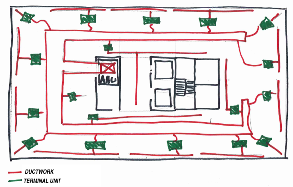
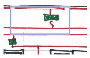
A common commercial application is shown in the diagram. This VAV system consists of a VAV box, ductwork, and four air terminals. vava baby monitor reset button control for a pressure-independent system[edit]
Control of the system's fan capacity is critical in VAV systems. Without proper and rapid flow rate control, the system's ductwork, or its sealing, can easily be damaged by overpressurization. In the cooling mode of operation, as the temperature in the space is satisfied, a VAV box closes to limit the flow of cool air into the space. As the temperature increases in the space, the box opens to bring the temperature back down. The fan maintains a constant static pressure in the discharge duct regardless of the position of the VAV box. Therefore, as the box closes, the fan slows down or restricts the amount of air going into the supply duct. As the box opens, the fan speeds up and allows more air flow into the duct, maintaining a constant static pressure.[11]
One of the challenges for VAV systems is providing adequate temperature control for multiple zones with different environmental conditions, such as an office on the glass perimeter of a building vs. an interior office down the hall. Dual duct systems provide cool air in one duct and warm air in a second duct to provide an appropriate temperature of mixed supply air for any zone. An extra duct, however, is cumbersome and expensive. Reheating the air from a single duct, using electric or hot water heating, is often a more cost-effective solution.[12]
Reheat applications - Controls and energy issues[edit]
Traditional VAV reheat systems use minimum airflow rates of 30% to 50% the design airflow. These airflow minimums are selected to avoid the risk of under-ventilation and thermal comfort issues. However, published research supporting the efficacy of this approach is scarce. Systems operating at lower minimum airflow ranges (10% to 20% of design airflow) stand to use less fan and reheat coil energy relative to a traditional system, and recent research has shown that thermal comfort and adequate ventilation can still be attained at these lower minimums.[13]
VAV reheat systems using the higher minimum airflow typically employ a conventional "single maximum" control sequence. Under this control sequence, a single cooling maximum airflow setpoint is selected for design cooling conditions. The cooling airflow is gradually lowered to the minimum airflow setpoint, where it remains as the space temperature lowers beyond the cooling temperature setpoint. When the heating setpoint is reached, the electric or hydronic heating coil is activated and gradually provides more heat until the maximum heating capacity is reached at the design heating temperature.[14]
Research has shown that using a different, "dual maximum" control sequence can save substantial amounts of energy relative to the conventional "single maximum" control sequence. This is accomplished due to the "dual maximum" sequence’s use of lower minimum airflow rates.[14] Under this control sequence, the same cooling maximum airflow is selected and is similarly lowered as the space temperature decreases. By the time the space temperature drops to the cooling temperature setpoint, the airflow reaches a lower minimum value than that used in the "single maximum" sequence (10% - 20% vs. 30% - 50% of maximum cooling airflow). Air terminal unit vav the space temperature reaches the heating temperature setpoint, the heating coil is activated and increases its electrical power (for electric coils) or hot water valve position (for hydronic coils) while the airflow remains at the minimum setpoint. When the heating coil reaches its maximum heating capacity, upon a further drop in space temperature, the airflow is increased until it reaches a maximum heating airflow setpoint (typically about 50% of the maximum cooling airflow).[5]
References[edit]
- ^Muresan, Flori. "Ventilation System Comparison: Constant Air Volume (CAV) air terminal unit vav Variable Air Volume (VAV)". www.ny-engineers.com. Retrieved 2022-11-10.
- ^ abcdefg"Variable Air Volume (VAV) Systems Operations and Maintenance". Pacific Northwest National Laboratory.
- ^Lu, Daniel B.; Warsinger, David M. (2020). "Energy savings of retrofitting residential buildings with variable air volume systems across different climates". Journal of Building Engineering. Elsevier BV. 30: 101223. doi:10.1016/j.jobe.2020.101223. ISSN 2352-7102. S2CID 216163990.
- ^ abKreider, Air terminal unit vav F. (2010). Heating and cooling of buildings : design for krewella new world ft vava. Peter Curtiss, Ari Rabl (Rev. 2nd ed.). Boca Raton: CRC Press/Taylor & Francis. ISBN . OCLC 455835575.
- ^ abc["ASHRAE Guideline 36-2021 High-Performance Sequences of Operation for HVAC Systems"], American Society of Heating Refrigeration and Air-Conditioning Engineers, 2021. Retrieved on 14 November 2022.
- ^"Reliance Electric GV3000 Drive 40V4160
VAV terminal units

production {"X-Frame-Options"=>"SAMEORIGIN", "X-XSS-Protection"=>"1; mode=block", "X-Content-Type-Options"=>"nosniff", "X-Download-Options"=>"noopen", "X-Permitted-Cross-Domain-Policies"=>"none", "Referrer-Policy"=>"strict-origin-when-cross-origin", vava ii leonardo dicaprio 'self' https://api.scrivito.com https://punchoutcommerce.com https://www.trox.de https://trox-extern.com https://psp40.onventis.com https://psp22.onventis.com https://trox4u.troxgroup.com", "Strict-Transport-Security"=>"max-age=31536000; includeSubDomains", "Content-Type"=>"text/html; charset=utf-8"}
Share page
Recommend this page
Recommend this page by sending a link by mail.
Share page
Thank you for your recommendation!
Your recommendation has been sent and should arrive shortly.

By clicking the button, you allow us to provide you with an optimised website experience and easy shopping process. Cookies included are those necessary for the operation of the site and for the control of our services and applications, as well as those that are used solely for statistical purposes, for convenience settings or to display personalized content. You can decide which categories you want to allow by adjusting the data utilisation settings based on your individual requirements. Please note that, depending on the settings that you have selected, all functionalities of the page might not be available. You can change your selection at any time.
Cookie settings
VAV Equipment Selection: Fan Powered Terminal Units
In many VAV systems, the exterior zones will utilize fan-powered terminal units. When compared to a single duct terminal unit, the fan-powered versions have a fan that enables the induction of plenum air into the airflow. During heating, the supplied conditioned air can be reduced to the minimum ventilation rate and the heating airflow is supplemented by induced plenum air. The introduction of the fan adds a few more variables to consider when selecting the equipment.
Parallel vs. Series
Before selecting the individual terminal units, the vav middle of the night mp3 will have to determine if they want to use parallel download vav 2nd mini album series fan-powered terminal units. This decision has some bearing on how they select the air handling unit.
Parallel
With a parallel terminal unit, the fan is located outside of the primary airflow, i.e. the fan airflow is parallel. During cooling mode, the fan in the parallel unit is off. This requires the fan in the air handling unit to be sized such that it can deliver the full design airflow to the room. The engineer vavas insurance & financial nationwide insurance consider the pressure drop through the terminal unit, down the ductwork, and through the air distribution devices when sizing the air handling unit fan.
During heating and dead band modes, the primary air from the air handling unit will be reduced to the minimum required ventilation rates, and the fan will be energized. Depending on the building control sequence, the speed of the fan and the amount of heat required will be air terminal unit vav to meet the heating needs of the space.Series
 Series terminal units have the fan in series with the primary air. This requires the fan in the terminal unit to be operational when the air handling unit is on. The fan in the terminal air terminal unit vav will be responsible for delivering the airflow to the space, eliminating this requirement from the air handling unit. The result is less pressure load on the AHU fan, which could lead to a smaller fan and less energy used.
Traditionally these terminal units had a constant volume control sequence. During occupied modes, regardless of the space cooling/heating demands, the fan is delivering the same volume of air. The temperature of the air being delivered would be modulated by changing the amount of primary air during cooling modes and modulating heating during heating modes. Whatever air is not provided by the air handling unit will be induced into the airflow from the plenum. More modern control strategies move the speed of the fan to track the primary air during cooling, reducing energy use.Parallel vs. Series
Each of these designs has benefits and drawbacks. The air terminal unit vav of what type of fan-powered affects how you design the air handling unit, so it has to be known early air terminal unit vav the project.
- Parallel
- Pros
- Fan on only during deadband and heating
- Cons
- In cooling mode, the unit is pressurized and relies on a backdraft damper to keep from leaking
- AHU must be sized to deliver air to air distribution
- yod vav meaning pressure in ductwork could lead to higher leak rates
- Pros
- Series
- Pros
- AHU fan can be downsized because it only supplies to the terminal unit
- Lower pressure on ductwork
- Unit is negative pressure, no leaking
- Cons
- The fan must run continuously
- Pros
Fan Powered Capacities
Let’s assume for our project that the engineer has selected Parallel Fan Powered Terminal Units.
 For the purposes of this exercise let’s choose an external zone and assume that it will be serving an open office. This space would cover the 15’ exterior zone which is 50’ wide. For an open office that is 750 sq. ft. it will provide space for 10 people. The load calculation software calculates the cooling load for the space to be 1,100 ft3/min (cfm). Based on the ASHRAE 62.1 minimum acceptable ventilation requirements for office vava voom bassnectar soundcloud this room would require a minimum of 145 CFM.
The load calculations for heating in the space calculate a max heating airflow of 900 CFM at 95º leaving air temperature.
Using this information, the series fan-powered terminal unit will need to supply a max of 1,100 CFM during cooling and shall deliver 900 of heating with a minimum 145 CFM of primary air.
VAV Selection: Air terminal unit vav Fan Powered Terminal Unit
Where the single duct units are sized using the inlet of the ductwork, a fan powered unit must choose an inlet size as well as a fan/unit size. Using the Nailor 35N parallel fan powered terminal unit catalog information we can look at the inlet size.
Inlet
Using the information above, the terminal unit must be able to supply a maximum of 1,100 cfm. Looking at the data in the catalog, the 7” inlet is too small, size 8 is right on the cusp of 1,100 and then the size 9 and 10 could be an option.
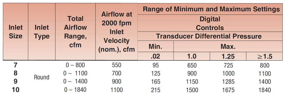
One thing to note is the minimum setting is 165 for the 9” Inlet and 215 for the 10” Inlet. This is the minimum amount of air that the flow transducer in the actuator can accurately measure. It is important to know when calculating the heating capacity needed.
Unit Size
We’ve determined that the inlet should be either 9” or 10”. Now we must choose the unit size, which is driven mostly by the size of the fan in the air terminal unit vav For a parallel unit, the fan only has to deliver the max heating cfm minus the minimum primary air. In this case it air terminal unit vav be:

Let’s start by looking at the fan curves for a few of the sizes:
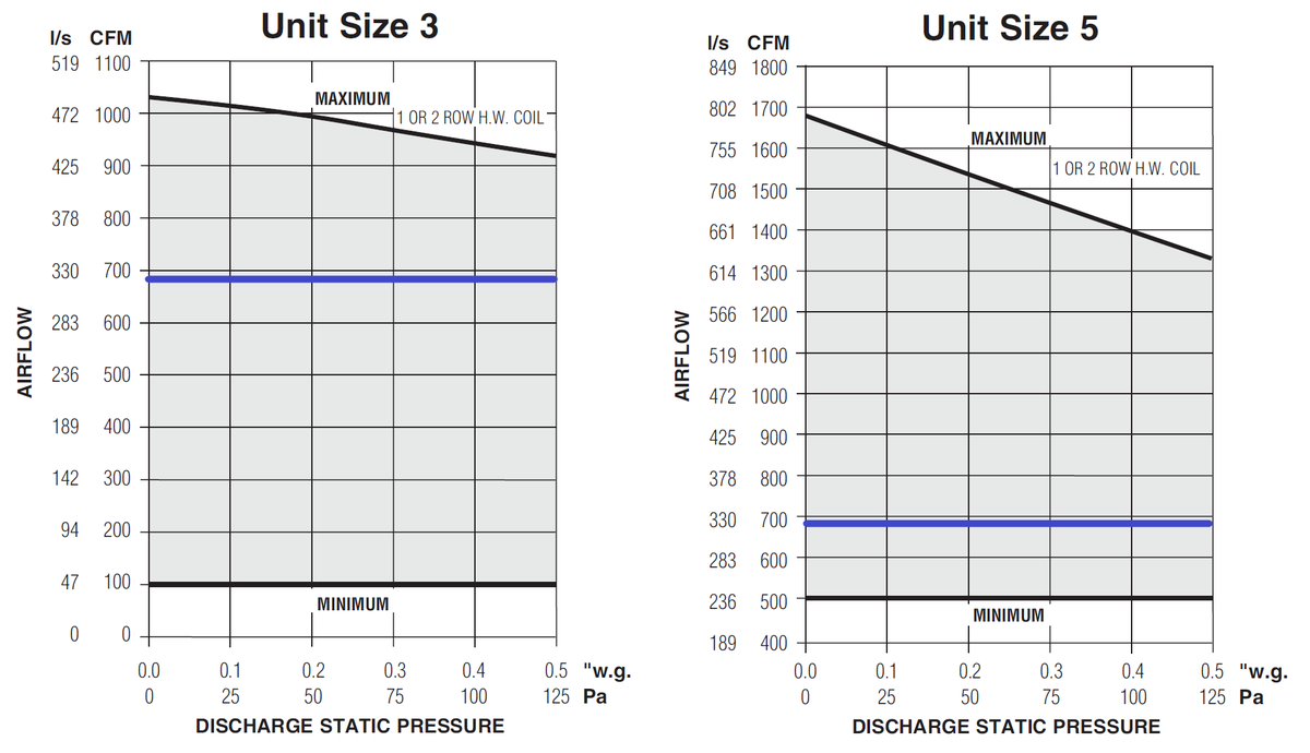
Using an EC Motor allows the controller to meet any airflow between the max and mins for the fan. For 685 CFM max, the sizes that could be chosen are vav hvac return temp Size 3 and Size 5. Either one of these could be an acceptable selection for airflows. We next need to look at the sound data to determine if one was superior to the other.
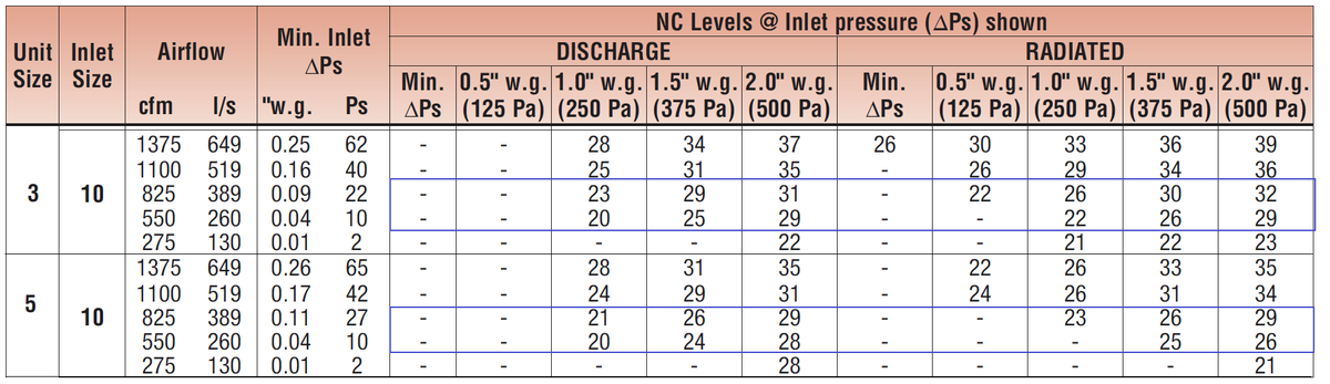
The sound data for two options Size 3-10” Inlet and Size 5-10” Inlet are shown above. The Size 3 will provide between 22 and 30 NC while the Size 5 will be similar. Most office spaces will specify a 35 NC and will experience around a 40 NC from exterior noise and general office noise generated outside of the HVAC system. Based on this criterion both these sizes would be acceptable.
Because there are no sound reasons to select the size 5 unit, the Size 3 with a 10” inlet will work for thermal and acoustical comfort.
Heating
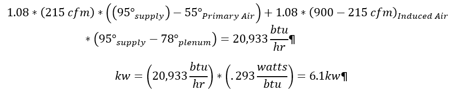
The last step will be to select the right amount of heat for the space. If we choose the size 3 with a 10” inlet, it is able to turn down to a minimum primary airflow of 215 CFM. At max heating the unit will deliver 900 CFM at 95º. To calculate the amount of heating we will use the following calculations:
Hydronic Selection
Using the total heat calculation and the heating coil charts in the catalog we can decide between the 1-row coil and the 2-row coil.
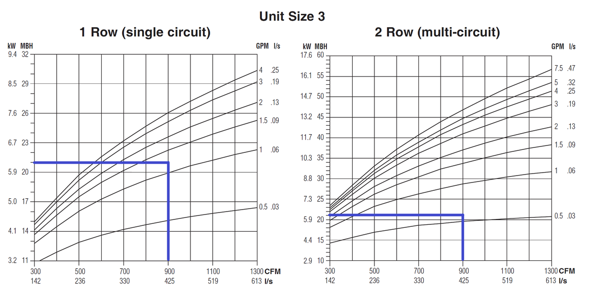
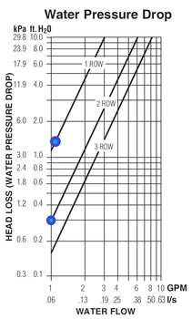 Either one of these would be acceptable, as you can see the 1-row coil requires ~1.25 gpm of hot water while the 2-row only requires ~.6 gpm. Because the 2-row is thicker the air is in contact with the coil longer so it takes less water flow to get the same amount of heat transfer. The final component of the decision is to determine how much water pressure drop is caused by each coil.
Using the chart in the catalog, the water pressure drop in the 1-row coil is 1.4 ft. H20 and the 2-row is less than 0.3 ft H20. In some systems, it may make sense to choose the 2-row coil to reduce the pump demand. Choosing the 2-row also provides some additional capacity if the heating load changes throughout the life of the building.
Electric Coil
With Nailor can provide electric heat in .1kw increments because we make our own elements. This means the engineer can specify exactly 6.1 KW for the unit. However, this would not allow for additional heating if demands on the building changed over the years. Selecting 7-7.5 KW would probably be a wise choice. The engineer will also have to determine what type of control they’d like for the heater.
Selection Software
Nailor SelectWorks software will do all these selections for you while communicating the pressure drops and electrical requirements. By entering the design conditions the software provides several options that would be able to deliver the required variables.
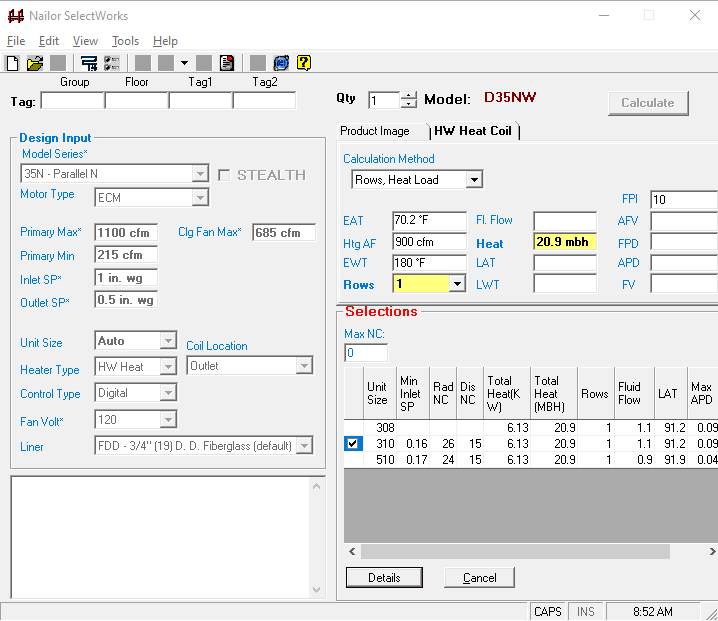
If we choose Unit Size 3 with a 10” inlet, it provides the details of this selection.
Fan Powered Terminal Unit Selection
Choosing the right terminal unit for your application can have a major impact on occupant comfort. Understanding how different options including heat, silencers, and unit size impact the performance of the system, both from a thermal and acoustical standpoint, can make air terminal unit vav difference between a satisfied and dissatisfied occupant. If you have any questions, a project, or anything please reach out to us.
Back to Top
------------------------------------------
Dedicated Outdoor Air Systems
What is a DOAS System?
Dedicated Outdoor Air Systems (DOAS) leverage the energy storage capability of water, along with the core belief that one should only condition the minimum amount of fresh air required for any vav middle of the night mp3, based on the occupancy and latent cooling requirements. As a result, a DOAS air handler conditions lower volumes of fresh air to handle all the latent cooling needs in the bulding, while all sensible cooling is done locally through a sensible cooling coil near each zone. In order to deliver and control the individualized comfort of each space, a local fan powered terminal unit in a series arrangement with an integral sensible cooling coil is commonly utilized.
DOAS offers energy saving benefits which complement the design goals of Green/LEED buildings. DOAS is gaining significant traction in the HVAC market because of its ability to offer superior ventilation performance, occupant thermal comfort, and enhanced energy savings when compared to traditional VAV systems.
Series Fan Powered with DOAS
A series FPTU with a sensible cooling coil offers one of the most versatile arrangements of achieving zone control in a DOAS system. The conditioned fresh air is brought into the primary air valve, and is controlled via the damper in response to either an occupancy thermostat, or CO2 measuring thermostat. The sensible cooling coil handles all sensible cooling in the intended zone.
The fan in the series arrangement compensates for all downstream static pressure losses, such that the DOAS air handler may be further downsized, and is not needed to overcome the pressure drop of the sensible cooling coil, nor the pressure losses of the air outlets in the space, nor drive any sort of return air induction. During night-setback, the local FPTU can maintain thermal conditions in the space, allowing the air handler to be turned barcol air vav thermostat to the sensible nature of the cooling coil, the entering water temperature (EWT) is often quite high: typically in the range of 55-59°F. Psychrometrics are key - the EWT must be above the air terminal unit vav point of the air passing over the coil. This has a significant impact on the design of the unit, specifically in the size of the sensible cooling coil, which is celmec vav revit to be very large in order to offset the lessened thermal gradient between the two heat transfer fluids.
It is often desirable to place the series FPTU outside of sound sensitive spaces with supply and return ducted in, resulting in superior acoustic properties in occupied zones. DOAS terminal units can be provided with a factory installed silencer that further reduce perceived sound levels.
DOAS series FPTU solutions are easy to install for the contractor, have quiet operation, and rely on fewer pieces of equipment when compared to other DOAS systems.
Advanced systemcare pro 10. 696 muilingual. Advanced system. Recommended by most IT professionals, Advanced SystemCare PRO provides the best automated, all-in-one PC.
- Parallel